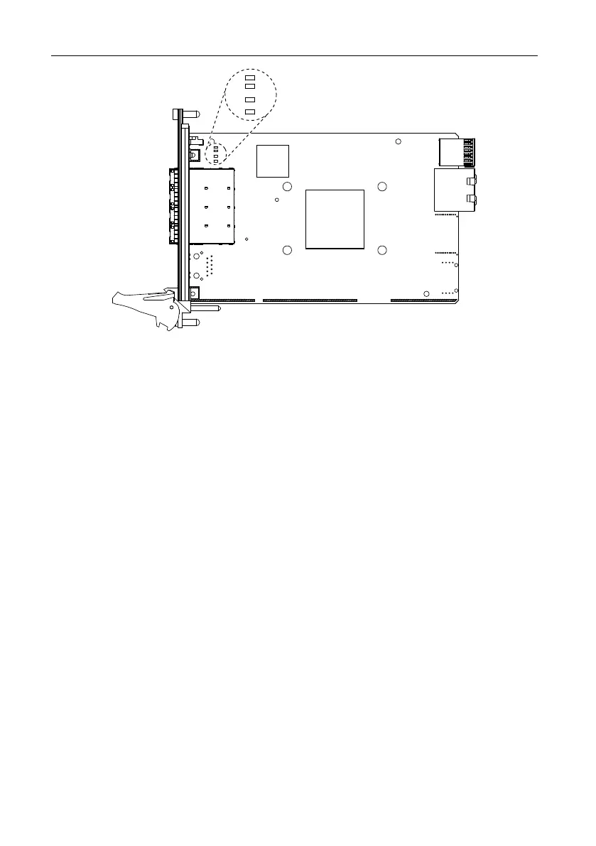
Figure 14. Backplane Link Status LEDs
The Backplane Link Status LEDs report the status of the PCI Express links established
between any PCI Express switches that reside on the backplane of the chassis that the
PXIe-8398 or PXIe-8399 is controlling. In some cases, the link is with the peripheral boards
installed in the chassis passive slots.
The chassis backplane architecture determines the PXIe-8398 and PXIe-8399 link
configuration. Refer to the chassis documentation for more information about its backplane
PCI Express link topology to the controller slot, as well as identifying any passive PXI
Express slots. A passive slot has a direct copper path to the controller slot instead of being
routed through a backplane PCI Express switch. Peripheral products installed in these slots
determine the actual link established to the PXIe-8398 or PXIe-8399, and the corresponding
backplane link status LED is set appropriately.
For a 4-link backplane, the LEDs represent links 1, 2, 3, and 4 from top to bottom. For a 2-link
backplane, the top two LEDs represent link 1 (x8 max), and the bottom two LEDs indicate the
status of the first eight lanes of link 2 (x16 max).
For the PXIe-8394, the top two LEDs indicate the status of the backplane link, which can be
up to x8 (eight lanes). The bottom two LEDs are unused.
PCIe-8398 Onboard LEDs
The PCIe-8398 also has several onboard LEDs that provide additional information about the
PCI Express link status.
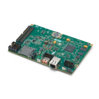
As shown in the following figure, there are six LEDs on the upper right corner of the
secondary, or back side, of the board. Two of the LEDs provide link status information. The
Port 0 LED reflects the status of the card edge connector and typically is solid green. Port 24 is
MXI-Express Gen-3 x16 User Manual | © National Instruments | 21
 Loading...