EasyManua.ls Logo

Navien NFB Series User Manual

Navien NFB Series
232 pages
To Next Page IconTo Next Page
To Previous Page IconTo Previous Page
Page #168 background image
56 Ventilation de la chaudière
Remarque
Lorsque le commutateurDIP 2 n°8 de la carte
PCB est réglé à OFF (désactivé) (par défaut),
la chaudière ne fonctionne pas sans qu’un
thermostat d’évacuation soit installé.
Lorsque vous réglez le commutateur DIP PCB 2 n° 8
à ON (activé), assurez-vous que de la tuyauterie de
PVC-C, de polypropylène ou d’acier inoxydable est
utilisée pour la ventilation d’évacuation.
1 2 3 4 5 6
O
N
O
N
1 2 3 4 5 6 7 8
ATTENTION
Cette chaudière est munie d’un contrôle intégré pour
limiter la température d’évacuation à 65 °C (149 °F). Par
conséquent, la chaudière peut être ventilée avec du PVC
calibre40.
Dans le cas d’une utilisation dans des températures élevées,
la température d’évacuation peut excéder 65 °C (149 °F).
Dans ce cas, vous devez utiliser du PVC-C de calibre 40 ou
80, du polypropylène approuvé ou de l’acier inoxydable
approuvé aux États-Unis ou un conduit de ventilation du
gaz spécial de type BH de classe IIB (PVC-C) ou de classe
IIC (polypropylène/acier inoxydable) conforme à la norme
ULC-S636 au Canada.
Lorsque des conduits de ventilation de 5,08 cm (2 po)
sont utilisés, si la température d’évacuation dépasse 65°C
(149 °F), le premier 0,91m (3 pi) du conduit doit être en
PVC-C (installé sur place). Dans les systèmes avec conduits
de 7,62cm (3po), les premiers 12,7cm (5po) du conduit
doivent être en PVC-C.
Les composantes d’évent en polypropylène ci-dessous sont
approuvées pour
l’utilisation avec cet appareil:
Duravent Polypro® SW (rigide)
2PPS-xxx (5,08cm [2po]) ou 3PPS-xxx (7,62cm [3po])
Centrotherm Innoflue® SW (rigide)
ISxx02xx (5,08cm [2po]) ou ISxx03xx (7,62cm [3po])
Centrotherm Innoflue® (flexible)
IFVL02xxx (5,08cm [2po])
IFSFC02 (adaptateur mâle rigide à flexible de 5,08cm [2po])
5.2 Sélection des matériaux des tuyaux de
ventilation
Les exigences en matière de ventilation sont différentes aux
États-Unis et au Canada. Lors de la sélection des matériaux des
tuyaux de ventilation, consultez le tableau suivant ou l’édition
la plus récente de la norme ANSI Z223.1/NFPA 54 ou CAN/CGA
B149.1, ainsi que tous les codes et règlements locaux applicables.
N’utilisez pas de tuyau en PVC avec noyau cellulaire (ASTM F891),
en PVC-C avec noyau cellulaire ou en Radel® (polyphénylsulfone)
comme conduit d’évacuation.
Pays
Matériaux recommandéspour les conduits
de ventilation
États-Unis
PVC/PVC-C calibre 40 ou 80 (pleine masse)
Polypropylène approuvé (PP)
Acier inoxydable approuvé (SS)
Canada*
Conduit de ventilation du gaz spécial de
type BH, classe IIA (PVC)
Conduit de ventilation du gaz spécial de
type BH, classe IIB (PVC-C)
Conduit de ventilation du gaz spécial de
type BH, classe IIC (polypropylène/acier
inoxydable)
* Pour une installation au Canada, la tuyauterie d’aération en plastique
installée sur place doit être conforme à la norme CAN/CGA B149.1
(dernière édition) et certifiée conforme à la norme des systèmes
d’évacuation du gaz de type BH, ULC-S636. Les composants de ce
système ne doivent pas être remplacés par d’autres systèmes de
ventilation ou d’autres tuyaux ou raccords non répertoriés. Tous les
composants en plastique et les apprêts et colles spécifiés du système de
ventilation certifié doivent provenir d’un seul fabricant de systèmes et ne
doivent pas être mélangés avec les pièces d’un autre fabricant.
Le raccord d’évent et la sortie de ventilation fournis sont des pièces
certifiées de la chaudière.
Ce produit est conçu pour l’utilisation de PVC en tant que
matériau par défaut pour les conduits de ventilation. Si la
température de l’eau du circuit de retour doit être supérieure
à 60°C (140°F) pour être renvoyée à la chaudière, vous
devez configurer le commutateurDIP (commutateurDIP2,
interrupteur8 en position ON). Sinon, la chaudière contrôlera
et maintiendra la température de combustion et d’eau
chaude sanitaire en-deçà de 65°C (150°F) et de 60°C (140°F),
respectivement.

Table of Contents

Question and Answer IconNeed help?

Do you have a question about the Navien NFB Series and is the answer not in the manual?

Navien NFB Series Specifications

General IconGeneral
TypeCondensing Boiler
Fuel TypeNatural Gas or Propane
Heat ExchangerStainless Steel
Vent TypeDirect Vent
Vent Diameter2" or 3"

Summary

Massachusetts Installation Requirements

Notice Before Installation

Key requirements and notifications for installation in Massachusetts.

Safety Information

General Safety Precautions

Details on DANGER, WARNING, and CAUTION symbols and their meanings.

About the Boiler

Included Items

Lists all components found in the boiler packaging.

Accessories

Lists optional accessories available for the boiler.

Specifications

Technical specifications for space heating ratings and water connections.

Components

Diagram showing key internal and external components of the boiler.

Dimensions

Diagrams and table detailing the boiler's physical dimensions and connections.

Rating Plate Information

Details on the boiler's rating plate and its importance for installation.

Installing the Boiler

Removing the Boiler from Packaging

Step-by-step guide for safely removing the boiler from its shipping pallet.

Choosing an Installation Location

Factors to consider for selecting an appropriate installation location.

Mounting the Boiler to the Wall

Instructions for securely mounting the boiler unit onto a wall structure.

Installing the System Piping

Installing a Space Heating System

Guidelines for correctly installing the space heating system.

Air Vent Installation

Proper installation procedure for the air vent connection.

Connecting the Condensate Drain

Steps for connecting the boiler's condensate drain line.

Condensate Neutralizer Kit

Details on the recommended condensate neutralizer kit and its installation.

Filling the System

Procedure for filling the boiler system with water.

Testing the Water System

Steps for performing a fill test on the installed water system.

System Application Examples

Illustrative examples of system piping configurations for various applications.

Electrical Connections Overview

General guidelines and diagrams for electrical connections.

Connecting the Gas Supply

Gas Pipe Sizing Tables

Tables for determining appropriate gas pipe sizing based on length and capacity.

Measuring Inlet Gas Pressure

Procedure for measuring and verifying the boiler's inlet gas pressure.

Venting the Boiler

Selecting a Vent Type

Guidance on choosing the appropriate vent type for the boiler.

Selecting Vent Pipe Materials

Approved materials and guidelines for vent pipe selection.

Measuring Vent Length

How to measure vent length and account for elbows.

Terminating the Vent

Guidelines and examples for proper vent termination.

Setting the DIP Switches

DIP Switch 1 Configuration

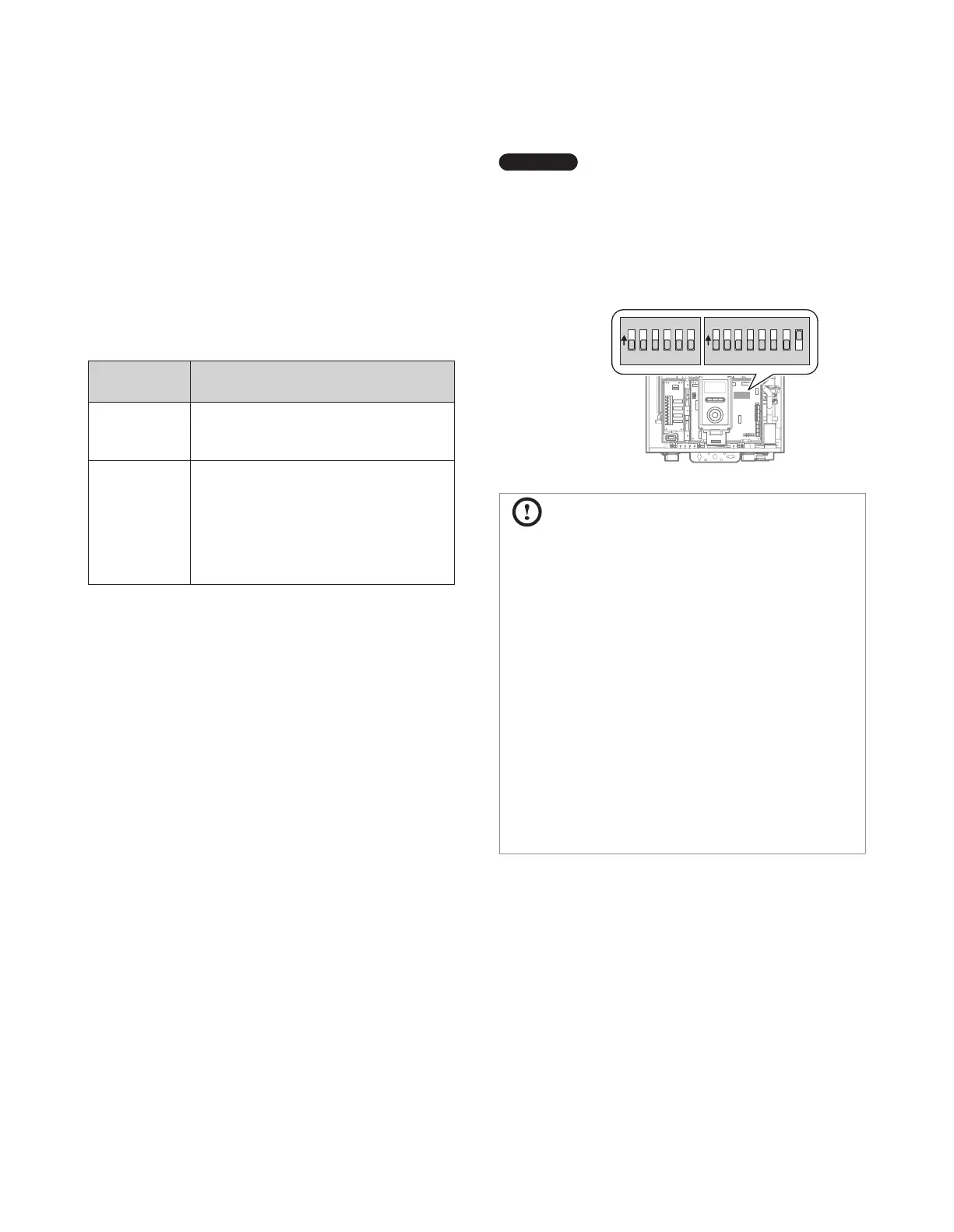
Settings for operation status and model/capacity.

DIP Switch 2 Configuration

Settings for gas type, temperature control, and thermostat.

Connecting the Power Supply

Installing a Cascade System

Connecting Water Supplies

Options for plumbing cascade systems and connecting water supplies.

Piping Sizes and Considerations

Guidelines for pipe diameters and flow rates in cascade systems.

Connecting Communication Cables

How to connect communication cables for cascade operation.

Configuring Communication Settings

Steps to configure communication settings for a cascade system.

Installing a Common Vent System

About the Common Vent System

Overview of the common vent system and its benefits.

Determining Common Vent Length

Method for calculating the required length of a common vent system.

Navien Backflow Damper (Back-draft Damper)

Installation and function of the Navien backflow damper.

Starting the Common Vent System

Procedures for assembling and starting the common vent system.

Connecting and Terminating Vent Pipe

How to connect and terminate the vent pipes for a common vent system.

Setting Up the Common Vent System

Steps for configuring the common vent system settings.

Common Vent Termination Clearances

Required clearances for common vent system terminations.

Installing a Condensate Drain

How to install a condensate drain for the common vent system.

Exhaust Vent Termination Clearances (For Direct Vent)

Clearances required for direct vent exhaust terminations.

Maintenance

Procedures for maintaining the backflow damper.

Installation Checklist

Operating the Boiler

Turning the Boiler On or Off

Basic procedure for powering the boiler on and off.

Adjusting the Temperature

How to adjust space heating and DHW temperatures.

Accessing Basic Menu Items

Navigating and using the basic menu functions on the control panel.

Accessing Advanced Menu Items

Accessing and using advanced menu settings and diagnostics.

Appendixes

Gas Conversion

Procedure for converting the boiler from Natural Gas to Propane Gas.

Wiring Diagram

Electrical wiring diagrams for the boiler system.

Ladder Diagram

Electrical ladder diagram illustrating system logic.

Outdoor Temperature Sensor

Installation guidelines for the outdoor temperature sensor.

Outdoor Reset Control

Information on the Outdoor Reset Control feature and its settings.

Component Assembly Diagrams

Diagrams and parts lists for boiler component assemblies.

Getting Service

Related product manuals