6.2.6 APS
1. Turn off the gas supply to the unit.
2. Disconnect the unit from the power supply.
3. Turn off the water supply to the unit.
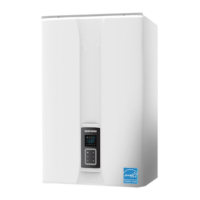
4. Remove the air pressure sensor wiring connector (Figure 19).
Figure 19
5. Remove the hose from the air pressure sensor.
Figure 20
6. Remove the 2 screws that attaches the air pressure sensor to
the burner assembly.
7. Pull out the air pressure sensor.
8. Replace the old air pressure sensor with the new part.
9. Reattach the air pressure sensor hose.
10. Connect the air pressure sensor wiring connector.
11. Place the front panel back onto the unit and secure it using the
4 screws.
12. Turn on water supply, power supply, and gas supply to the
unit.
NOTE
Confirm that the new air pressure sensor is in the proper
position before turning the unit back on.
6.2.7 Main Gas Valve
1. Turn off the gas supply to the unit.
2. Disconnect the unit from the power supply.
3. Turn off the water supply to the unit.
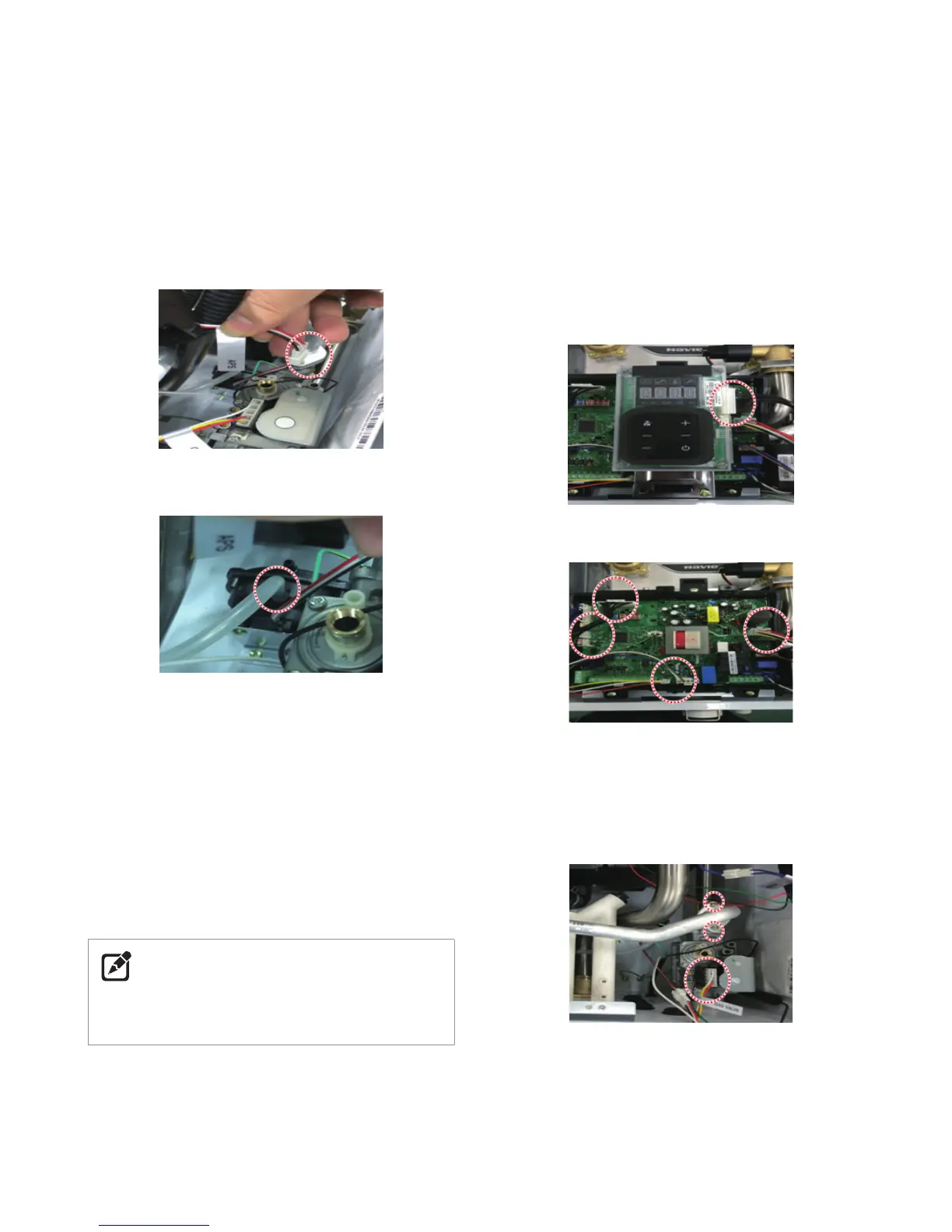
4. Remove the PCB (See page 126)
●
Disconnect wiring connector from the Front Panel.
●
Remove the 3 screws from bottom PCB bracket and upper
PCB bracket.
Figure 21
Disconnect wiring connector from the Front Panel.
Figure 22
Disconnect all wiring connectors from the PCB
Remove the 3 screws from bottom PCB bracket and upper PCB
bracket.
5. Remove the 2 screws and disconnect the wiring connector at
the gas valve.
Figure 23
 Loading...