 Loading...
Do you have a question about the NEC 2400 and is the answer not in the manual?
Identifies primary and secondary audiences for this document, including technicians and support personnel.
Outlines required knowledge of AT&T computer systems, switches, and installation procedures.
Explains the structure of the document, detailing the content of each chapter and appendix.
Details precautions to prevent electrostatic damage to equipment and ensure user safety during installation.
Explains factory assembly, load, and test processes for INTUITY hardware and software before shipping.
Guides on selecting an appropriate physical location for the Switch Integration Device (SID).
Illustrates connection diagrams for Intuity system integration with a NEAX switch.
Lists hardware components required for the Intuity system for NEAX integration.
Lists hardware components required for the Switch Integration Device (SID) for integration.
Details the specific NEAX 2400 MCI switch and related components required for integration.
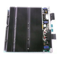
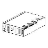
Describes the physical components of the SID, including front and rear panels.
Explains the SID software, covering menu forms, edit forms, and action forms.
Guides on specifying the number of voice mail ports for the SID to support and monitor.
Details how to match the SMDI message desk number with the voice mail system.
Explains configuring the CPID string for calling party information exchange.
Details configuring the MWI pad string for message waiting indicator information.
Explains enabling the INTUITY System to activate message waiting lamps.
Guides on setting the baud rate for the MCI link, ensuring it matches switch I/O card settings.
Details setting the baud rate for the Simplified Message Desk Interface (SMDI) link.
Guides on associating Logical Terminal Numbers (LTNs) with analog extension numbers for SID application.
Procedure for connecting an analog line from the switch to the SID's modem port for maintenance.
Instructions for connecting the MCI link between the NEAX 2400 switch and the SID.
Details connecting the MCI cable to the A25B 25-pair Amphenol cable for integration.
Instructions for connecting the Null cable and Y-cable to the SID's MCI digital port.
Procedure for connecting the SID to the INTUITY System using an RS-232 cable and adaptor.
Steps for connecting the SID's power cord and powering on the unit.
Lists prerequisites for SID software installation, including login and materials.
Procedure to stop the INTUITY voice system before loading SID software.
Step-by-step instructions for loading the SID Switch Integration Package from floppy disks.
Procedure to restart the INTUITY voice system to accept and process calls after software installation.
Instructions to enable the transfer feature in INTUITY AUDIX after system restart.
Details changing default settings on the Switch Link Administration screen for NEAX integration.
Procedure to stop and restart the INTUITY voice system to execute changes made on the Switch Link screen.
Guides on entering correct values in the System Translation screen for integration.
Configures analog lines for voice mail ports, assigning them to SID configuration extension numbers.
Assigns voice mail port extensions to a Uniform Call Distribution (UCD) group for call handling.
Explains how to create UCD groups and link them using the UCD Overflow feature.
Details configuring the MCI data link, including administering MWL, assigning ports, and defining ports as terminals.
Guides on configuring basic SID parameters like voice mail ports, message desk number, and CPID/MWI strings.
Associates LTNs with analog extension numbers, ensuring proper SID call integration.
Instructions for saving the SID configuration and starting the integration process.
Checks and corrects default settings for MCI and SMDI communication ports.
Covers adjusting system parameters like time/date and LCD contrast for the SID.
Guides on setting the SID's security level to control access to features and functions.
Details administering test subscribers on the NEAX 2400 MCI switch for performing acceptance tests.
Instructions for forwarding calls when a subscriber's extension is unanswered during acceptance tests.
Instructions for forwarding calls when a subscriber's extension is busy during acceptance tests.
Instructions for forwarding all calls for subscribers during acceptance tests.
Procedure for administering subscriber telephones for the INTUITY system cut-over process.
Guides for forwarding subscriber calls on ring-no-answer during cut-to-service.
Guides for forwarding subscriber calls on busy conditions during cut-to-service.
Guides for forwarding all subscriber calls during cut-to-service.
Lists common problems with the SID, their possible reasons, and remedies.
Explains how to access and interpret error messages recorded by the SID.
Allows observation of transactions on the SMDI data link connecting SID to INTUITY System.
Monitors transactions sent between the switch and the SID on the MCI data link.
Monitors calls processed, bad packets, and message waiting commands for system activity.
Displays performance measurements for SID call processing and message waiting activities.
Procedure to purge accumulated data for Statistics and Metrics views.
Covers configuring a hunt group for calls received by the INTUITY system.
Details administering message retrieval numbers for subscribers and system configuration.
Explains enabling voice mail and providing separate numbers for guest access.
Directs the switch to transfer unanswered calls to a hunt group or service.
Describes the Do-not-Disturb feature for lodging situations on some switches.
Explains changing coverage paths for guest extensions to the INTUITY system hunt group.
Strategy for entering guests into INTUITY Lodging as they check in.
Strategy to assign all guest stations to INTUITY Lodging simultaneously.