13
5.2 Dimensions and recommended clearances
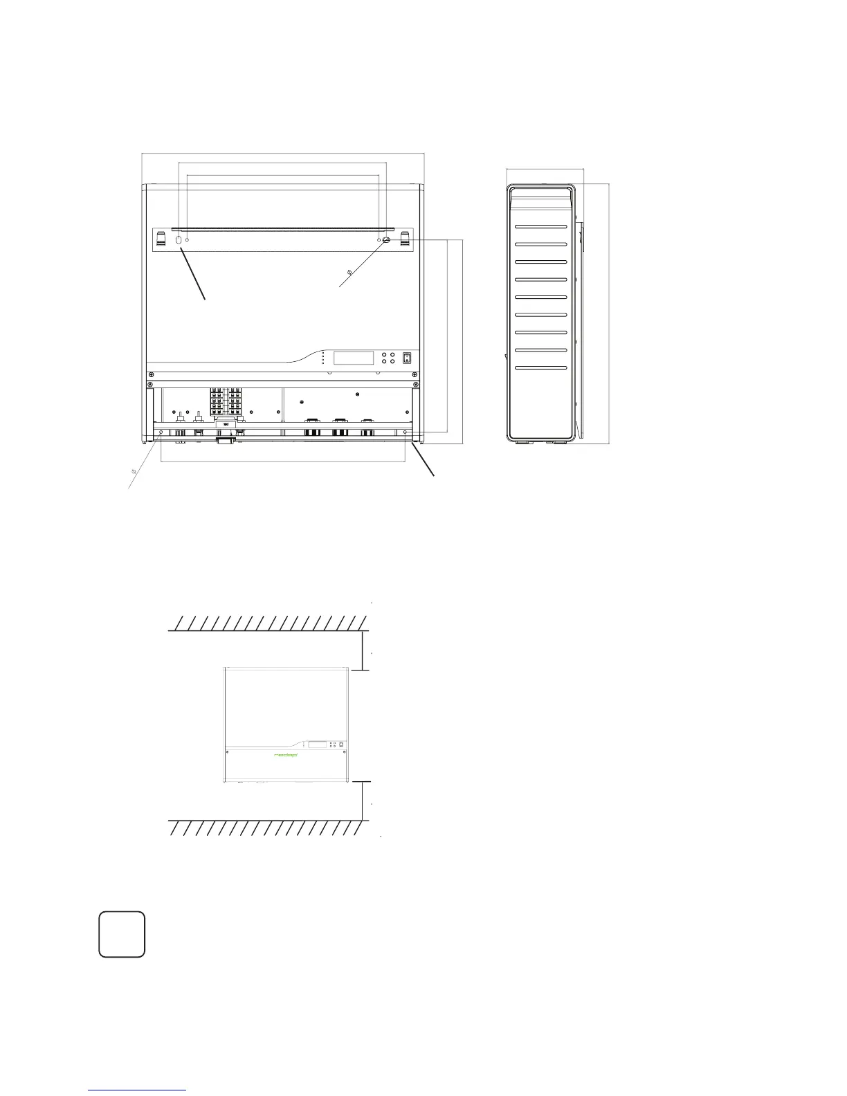
Mount the PowerRouter so that there is at least 300 mm of clearance at the top and
bottom of the PowerRouter.
Figure 5 External Dimensions of the PowerRouter (in mm)
Use the drill template for drilling the bracket and mounting holes (Nedap part-
number 5555426)
Ensure that there is sufcient clearance for the ow of the air around the
PowerRouter! In a normal operating environment with good ventilation, a
minimum of 300 mm clearance on top and bottom is adequate.
Local regulations may require larger working clearances.
Figure 6 Recommended clearance
min. 300 mm
min. 300 mm
Mounting holes (2 x)
Bracket holes (2 x)
i
370
544
470
370
393
max.
5,5
(2x)
400
max.
10
(2x)
501
149
 Loading...