50
Appendix G Install sheets
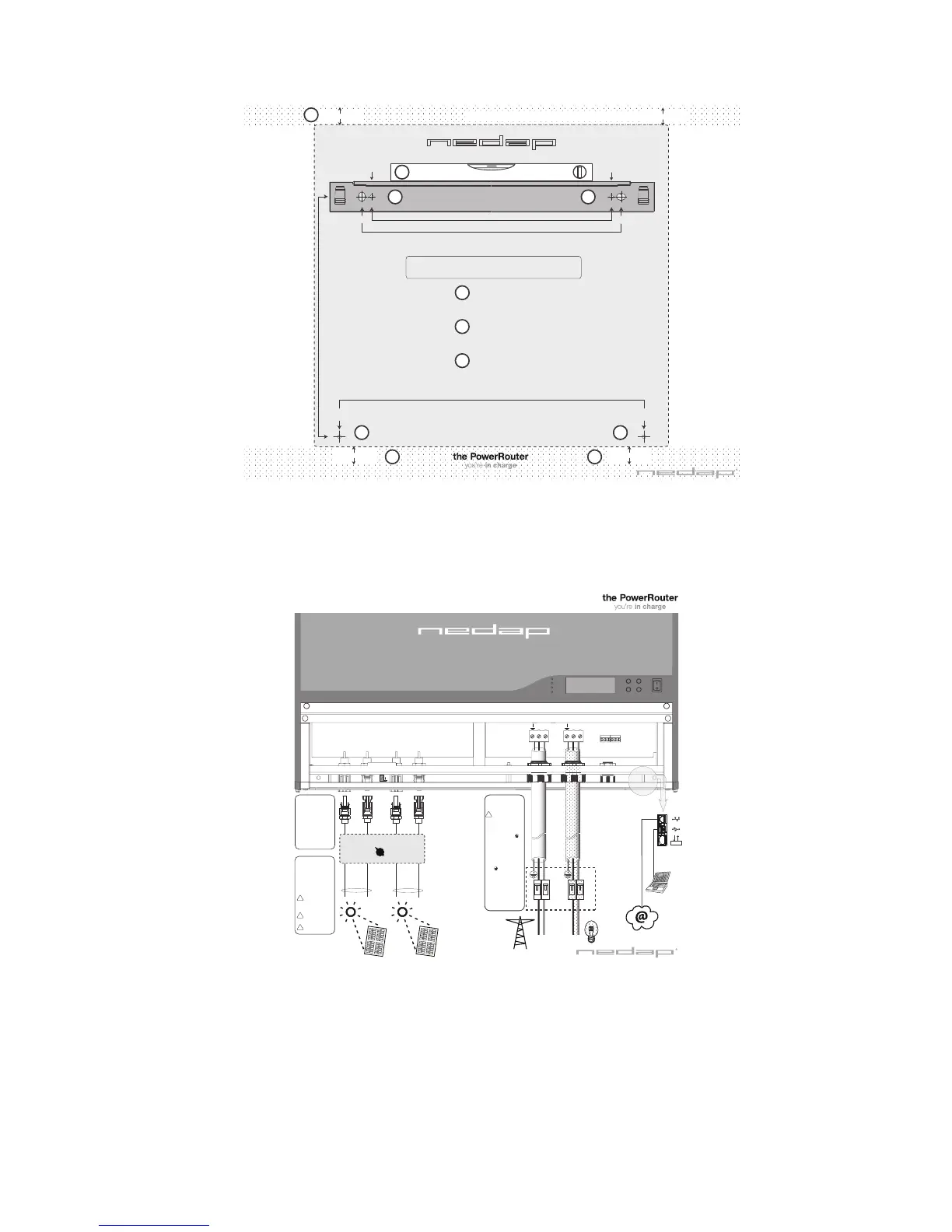
Figure 33 Drill template scale 1:1 (Nedap part-number 5555477)
Drill template is included to simplify the mounting of the Power-
Router.
Figure 34 Installation quick reference sheet (Nedap part-number
5277329)
Installation sheet is included to simplify the wiring of the Power-
Router.
NO
NO
NC
NC
grid
PowerRouter
Installation sheet PR50S Refer to installation manual Nedap part-number 5277337 for details
MAIN
BREAKER
BOX
AC
GRID
AC
LINE
OUT
N L N L
N L N L
4 mm
2
4 mm
2
4 mm
2
4 mm
2
minimum 3 x 2.5 mm
2
minimum 3 x 2.5 mm
2
Solar
o on
CAN
25 A 25 A 25 A 25 A
Manual installation sheet Nedap part-number 5277329 rev.0
String 1
String 2
+
-
+
-
optional breaker
minimum 3 x 2.5 mm
2
Sequence of connecting:
De-energize all energy
sources
1. Connect AC wiring
(Load / Grid)
2. Connect Solar wiring
3. Switch on dc-switches
4. Switch on ac-switches
(load / grid)
Wiring solar connection:
Connect MC4 string(s)
connectors to solar
terminals
or
Connect string(s) to
optional solar breaker
Breaker must have a
minimum rating of
600V dc and 15A cont.
Serial fusing may be
required.
Solar irradiated panel
generates high voltage
Wiring grid / load
connection:
Turn OFF the main breaker
in the main utility breaker
box
1. Connect the AC Line Out
ground wire to the AC Line
Out terminal labelled
2. Connect the AC Line L wire
to the AC Line Out terminal
labelled L
3. Connect the AC Line N wire
to the AC Line Out terminal
labelled N
4. Connect the AC Grid/Utility
ground wire to the AC
Grid/Utility terminal label-
led
5. Connect the AC Grid/Utility
Lwire to the AC Grid/Utility
terminal labelled L
6. Connect the AC Grid/Utility
N wire to the AC
Grid/Utility terminal label-
led N
Verify that all connections
are correctly wired and
properly torqued.
(min. 1.2 Nm. Max 1.5 Nm.)
optional
minimum 300 mm free area
minimum 300 mm free area
Drill template PR50S
1
1
1
1
Attach the mounting sheet with tape exact
horizontaly at the wall.
The PowerRouter has a minimum of 300 mm
free area at the top and the bottom.
Make sure that the wall you choose to mount the Power Router on is sturdy enough to support
its weight (15.5kg) over al long period of time and that the wall is plumb. The bracket may be
mounted on stone, brick or solid walls. Be sure to use the appropriate type of mounting hard-
ware for the wall material.
2
Drill bracket holes.
3
3
3
Drill mounting holes.
1
!
400 mm
470 mm
370 mm
370 mm
mounting drill hole
maximum ø5.5 mm
mounting drill hole
maximum ø5.5 mm
mounting drill hole
maximum ø5.5 mm
mounting drill hole
maximum ø5.5 mm
Refer to installation manual Nedap part-number 5277337 for details
minimum 300 mm free area
minimum 300 mm free area
2
2
Mounting bracket
mounting drill hole
maximum ø10 mm
mounting drill hole
maximum ø10 mm
Drill template PR50S part number 5555477 rev.0
 Loading...