23
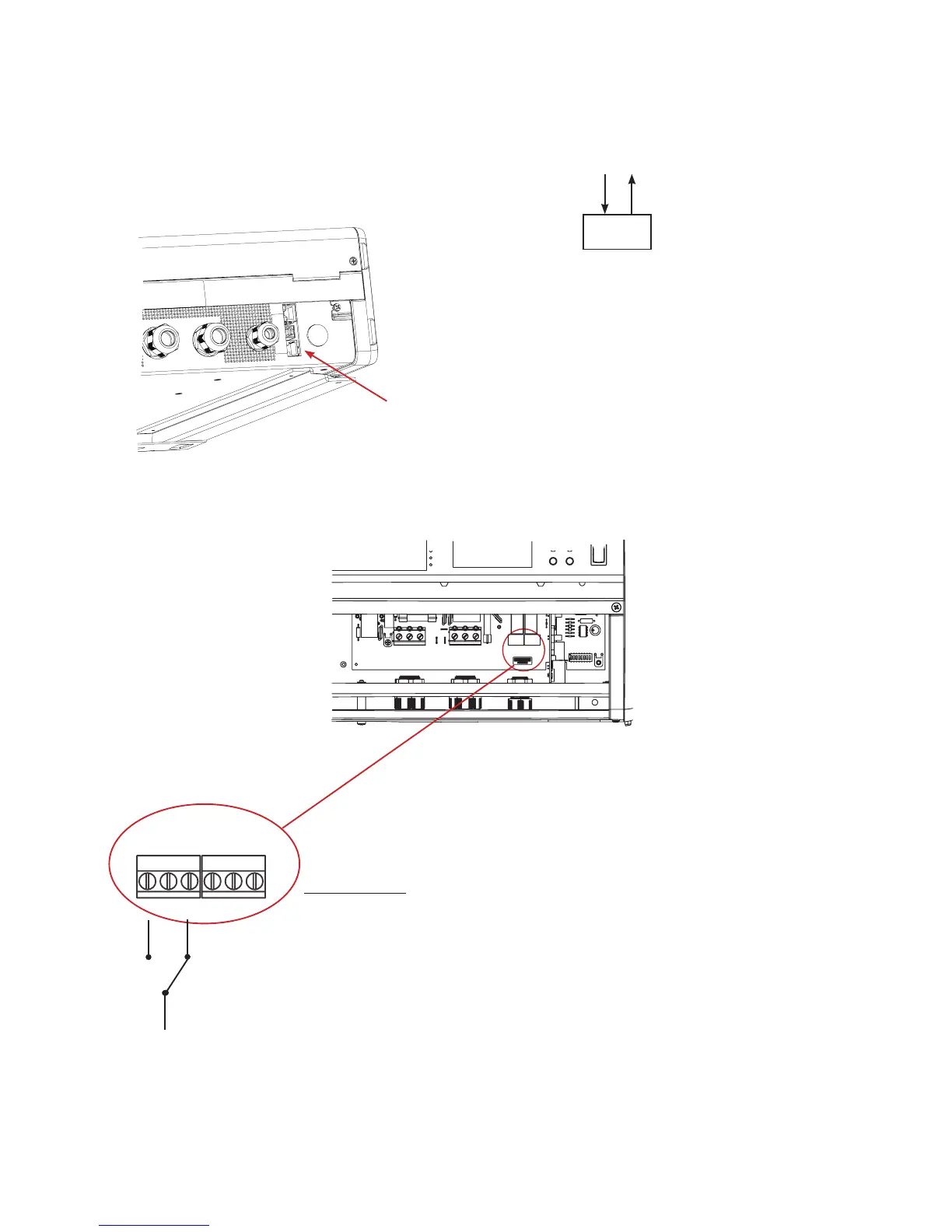
6.4 Wiring optional connections
This section describes the connection of the PowerRouter to the optional
connections.
CAN bus connection: for future use
Relay connection:
Figure 18 CAN bus port
CAN connector
Example:
Grid alarm:
• relay activation when grid voltage lower than 120V with a
delay of 5 seconds.
• relay deactivation when grid voltage higher then 210V with
a delay of 5 seconds.
Values are adjustable with the installation software tool;
see also Appendix B.
Figure 19 location of the relay
connectors
CAN
AC Grid/Utility
AC
The CAN bus is not intended for looping
to other PowerRouter units.
Line Out
NO
NC
grid
 Loading...