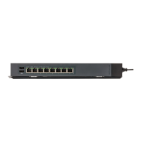
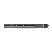
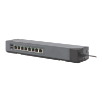
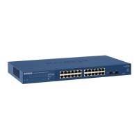
From the left to the right, the front panel contains the following components:
•
Sixteen independent 10/100/1000BASE-T RJ-45 ports, each with a left LED and a
right LED that, combined, indicate link, speed, and activity (see Status LEDs model
GSS116E on page 15).
•
A rectangular Power LED (see Status LEDs model GSS116E on page 15).
•
An AC power receptacle, placed at a 45-degree angle. (The switch integrates a fixed,
internal power supply unit.)
Status LEDs model GSS116E
The following table describes the RJ-45 port LEDs for ports 1–16 and the Power LED
on the front panel of model GSS116E. The Power LED is located to the right of port 16.
Table 2. Front panel LEDs for model GSS116E
DescriptionLEDs
Right port LEDsLeft port LEDs
A valid 1000 Mbps Ethernet port link is established.OffSolid green
The port is transmitting or receiving packets at 1000 Mbps.OffBlinking green
A valid 10 Mbps or 100 Mbps Ethernet port link is established.Solid greenOff
The port is transmitting or receiving packets at 10 Mbps or 100 Mbps.Blinking greenOff
No Ethernet link port is established.OffOff
The switch is powered on.Solid green
Power LED
Power is not supplied to the switch.Off
Back panel model GSS116E
The back panel does not contain any components other than a recessed Factory Default
button (see Factory Defaults button on page 18).
The following figure shows the back panel.
Figure 4. Back panel model GSS116E
Hardware Installation Guide15Hardware Overview
8-Port and 16-Port Gigabit Ethernet (PoE+) Smart Managed Plus Click Switch
 Loading...