RS HARDWARE SETUP PROCEDURE
System Manual RS Series Page 19 / 76
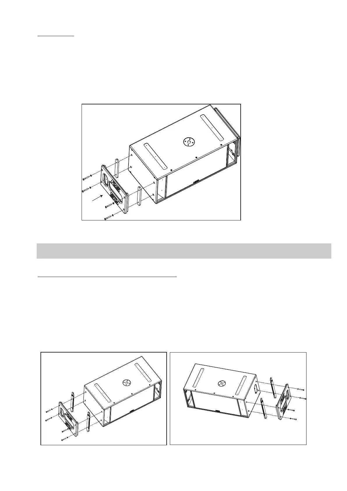
5.2.2 RS15 handles
Procedure
- Remove the four screws on each side of RS15
- Fill each screw hole with Loctite 243 or equivalent
- Position spacers and handles according to below drawing (vertical opening must be aligned with connector panel or owner’s
plate)
- Insert the four washers and screws provided with the RST-HANDLES15 kit and tight them
INSTALLING RS15 HANDLES
IMPORTANT
RS15 handles must not be used to fly RS15’s (through illegal use of straps for example)
5.2.3 RS15 Flying Plates with handles (touring applications)
Procedure
- Remove the four screws on each side of RS15
- Fill each screw hole with Loctite 243 or equivalent
- Position flying bars so that articulated link bars are opposite to skids, ie at the top of the cabinet
- Position handles according to below drawing (vertical opening must be aligned with connector panel or owner’s plate)
- Insert the four washers and screws provided with the RST-FLPLATES15 kit and tight them (torque value must be 10 Nm
minimum)
INSTALLING RS15 FLYING PLATES AND HANDLES
 Loading...