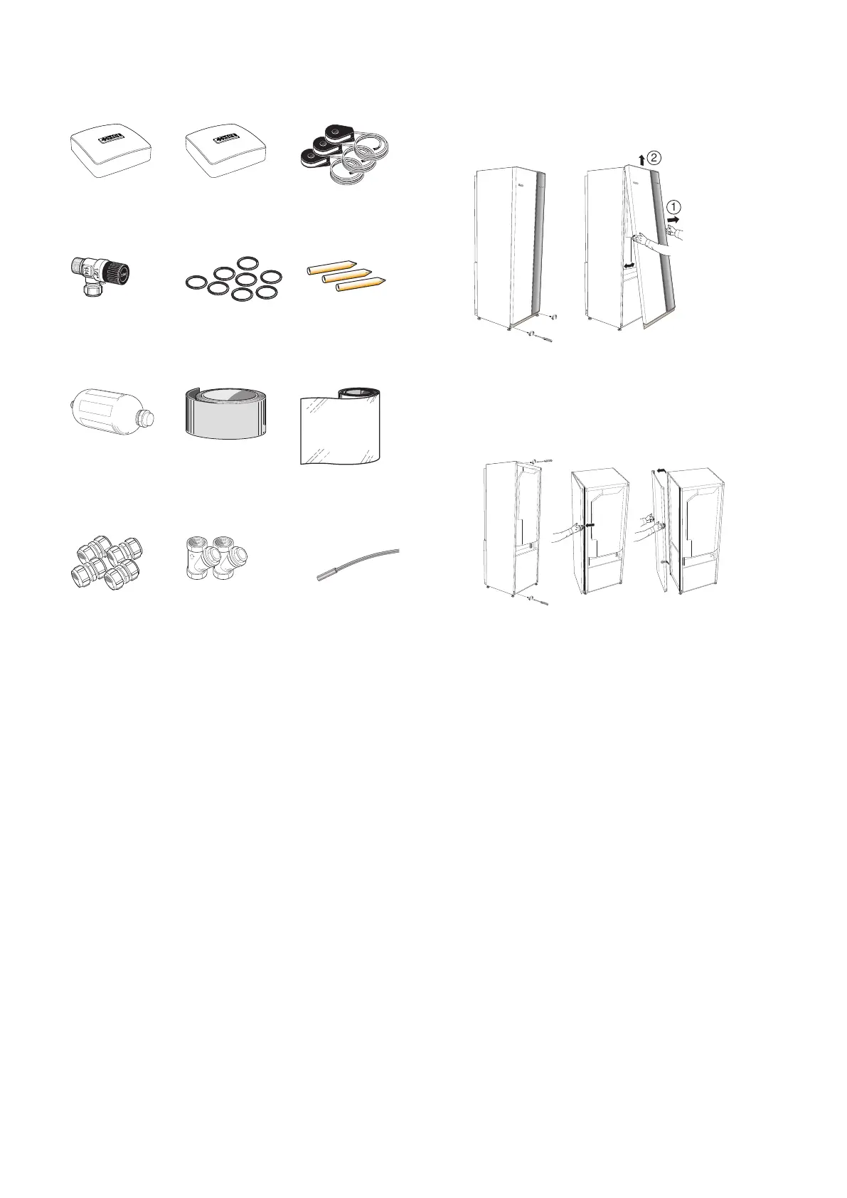
Supplied components
Current sensor
3 x
Room sensor
1 x
Outside sensor
1 x
Tubes for sensors
3 x
O-rings
8 x
Safety valve
0.3 MPa (3 bar)
1 x
Aluminium tape
1 x
Insulation tape
1 x
Level vessel
1 x
Temperature
sensor
3
WILO
LEK
LEK
WILO
WILO
2,5(22)
H - 50 - 2,5
TUV-SV-97-525
WILO
LEK
LEK
WILO
WILO
2,5(22)
H - 50 - 2,5
TUV-SV-97-525
Particle filter
6 – 10 kW
1 x G1
1 x G3/4
12 – 17 kW
1 x G1
1 pcs G1 1/4
Compression ring
couplings
6-10 kW
2 x (ø28 x G25)
3 x (ø22 x G20)
12 – 15 kW
5 x (ø28 x G25)
17 kW
3 x (ø28 x G25)
2 x (ø35 x G32)
LOCATION
The kit of supplied items is placed in packaging on top
of the heat pump.
Removing the covers
FRONT COVER
1.
Remove the screws from the lower edge of the
front panel.
2.
Lift the panel out at the bottom edge and up.
SIDE COVERS
The side covers can be removed to facilitate the install-
ation.
1.
Remove the screws from the upper and lower
edges.
2.
Twist the cover slightly outward.
3.
Move the hatch outwards and backwards.
4.
Assembly takes place in the reverse order.
NIBE F1145Chapter 2 | Delivery and handling8
 Loading...


