General
Pipe installation must be carried out in accordance with
current norms and directives.
F2120 can only operate up to a return temperature of
about 55 °C and an outgoing temperature of about 65 °C
from the heat pump.
F2120 is not equipped with external shut off valves on
the water side; these must be installed to facilitate any
future servicing. The return temperature is limited by
the return line sensor.
WATER VOLUMES
Depending on the size of F2120, an available water
volume is required to prevent short operating times and
to enable defrosting. For optimal operation of F2120, a
minimum available water volume of 10 litres times the
size number is recommended. E.g. F2120-12: 10 litres
x 12 = 120 litres.
NOTE
The pipe work must be flushed before the heat
pump is connected, so that any contaminants
do not damage the components.
Pipe coupling heating
medium circuit
• The heat pump must be vented by the upper connec-
tion (XL1) using the venting nipple on the enclosed
flexible hose.
• Install the enclosed particle filter before the inlet, i.e.
the lower connection (XL2) on F2120.
• All outdoor pipes must be thermally insulated with at
least 19 mm thick pipe insulation.
• Install shutoff and drain valves so that F2120 can be
emptied in the event of prolonged power failures.
• The supplied flexible hoses act as vibration dampers.
The flexible pipes are fitted so an elbow is created,
thus acting as vibration damping.
CHARGE PUMP
The charge pump (not included in the product) is
powered and controlled from the indoor module/control
module. It has a built-in anti-freezing function and must
therefore not be switched off when there is a risk of
freezing.
At temperatures below +2 °C the charge pump runs
periodically, to prevent the water from freezing in the
charge circuit. The function also protects against excess
temperatures in the charge circuit.
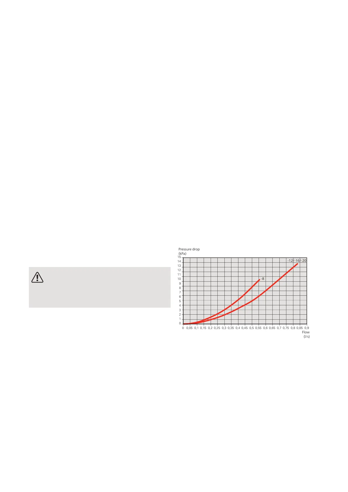
Pressure drop, heating
medium side
F2120-8, -12, -16, -20
0
1
2
3
4
5
6
7
8
9
10
11
12
13
14
15
0
0,05
0,1 0,15 0,2 0,25 0,3 0,35 0,4 0,45 0,5 0,55 0,6 0,65 0,7 0,75 0,8 0,85 0,9
Tryckfall
[kPa]
Flöde [l/s]
Tryckfall F2120
Pressure drop
(kPa)
Flow
(l/s)
-12/-16/-20
-8
NIBE F2120Chapter 4 | Pipe connections20
4 Pipe connections

 Loading...