Configuration using
DIP switch
The communication address for F2120 to the indoor
module / control module is selected on the base board
(AA2). DIP switch S1 is used for configuration of address
and functions. For cascade operation with SMO for ex-
ample, addressing is required. F2120 has the address
1 as standard. In a cascade connection all F2120 must
have a unique address. The address is coded in binary.
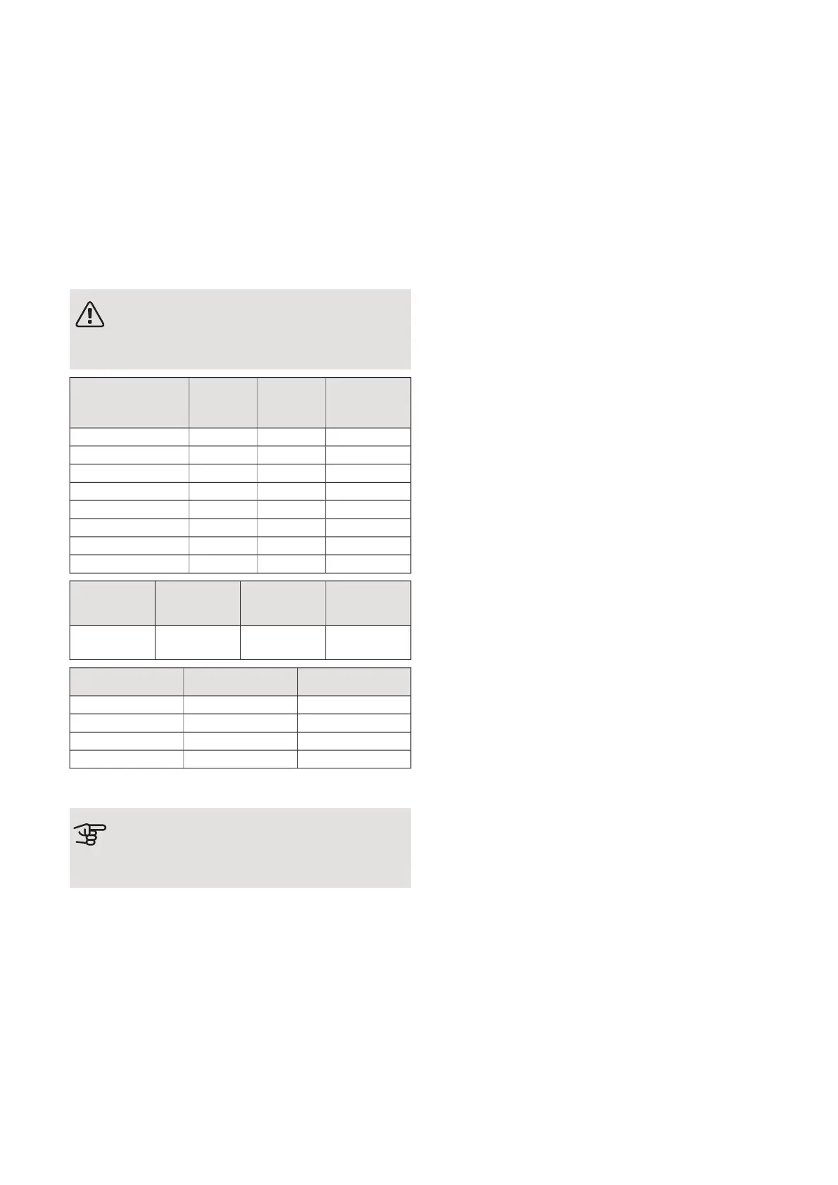
NOTE
Only change the DIP switches position when
the product is not powered.
Default set-
ting
Address
(com)
SlaveDIP S1 position
(1 / 2 / 3)
OFF01Slave 1off / off / off
OFF02Slave 2on / off / off
OFF03Slave 3off / on / off
OFF04Slave 4on / on / off
OFF05Slave 5off / off / on
OFF06Slave 6on / off / on
OFF07Slave 7off / on / on
OFF08Slave 8on / on / on
Default set-
ting
FunctionSettingDIP S1 posi-
tion
OFFPermits cool-
ing
ON4
Default settingSettingDIP S2 position
OFFOFF1
OFFOFF2
OFFOFF3
OFFOFF4
Switch S3 is the reset button that restarts control.
Caution
DIP S1 position 4 must be changed to ON in
order to run cooling
NIBE F2120Chapter 5 | Electrical connections24
 Loading...