Pag. 10 a 37
LP21/LP22 Installation instructions en Sensors
5 Description of connections
In the following section, the connections for the inputs and outputs are described.
5.1 Power supply
The detector can be operated with direct or alternating current, according to the requirements for Safety
Extra-Low Voltages (SELV) of Protection Class III.
Note the permitted power supply
Comply with the technical data and safety instructions!
The power supply is connected to the blue terminal block.
Fig.3: Power supply connection (blue)
5.2 Loop inputs
Up to two analogue inputs for the induction loops on the terminal block are located on the underside of the
traffic detector. The terminal block is either 2-pole or 4-pole, depending on the product variant.
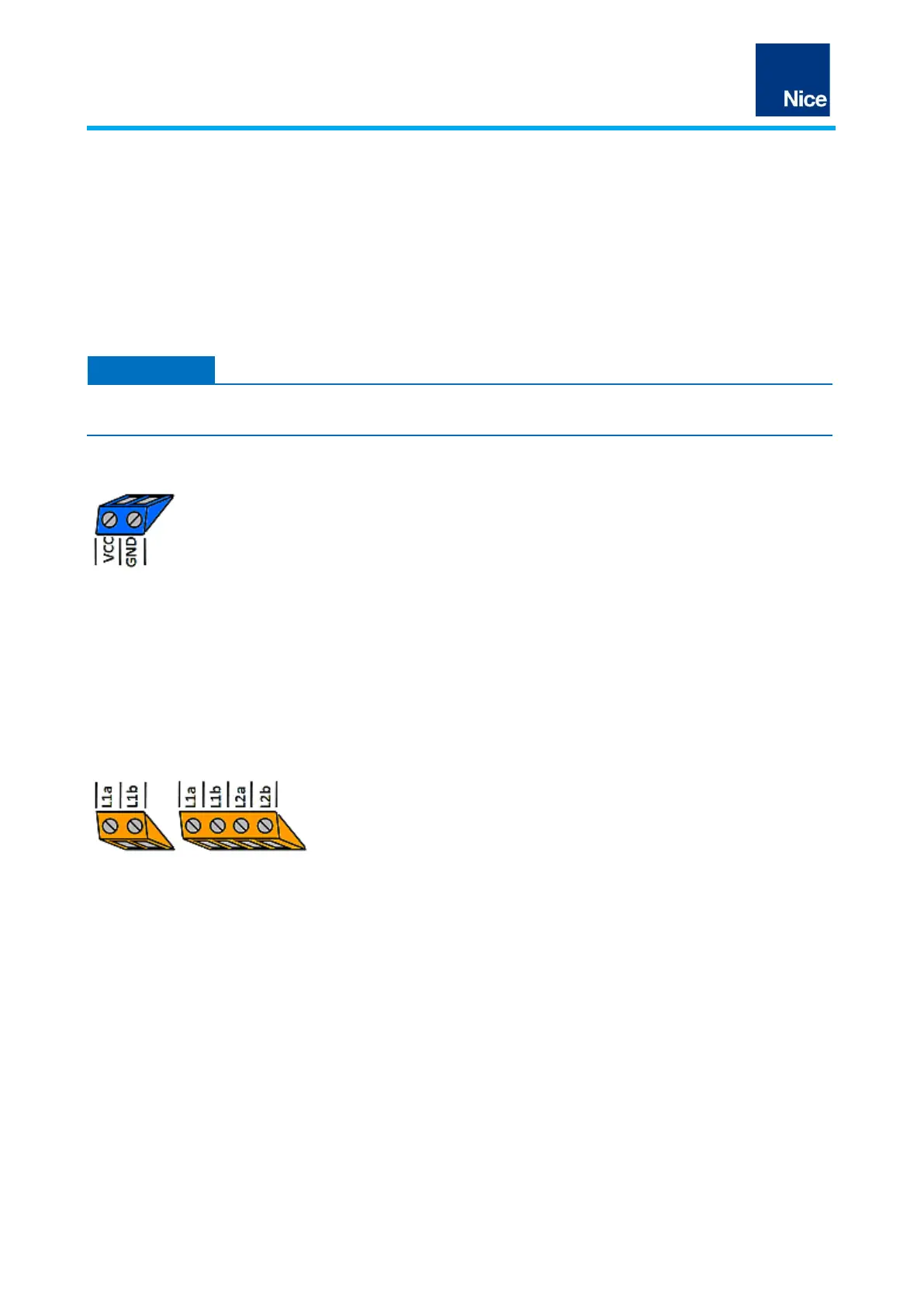
The induction loops are connected to the orange terminal blocks as shown in the illustration.
Induction loop channel 1 connections
Induction loop channel 2 connections
(dual-channel variant LP22)
Fig.4: Loop connections (orange)
 Loading...