Pag. 4 a 37
LP21/LP22 Installation instructions en Sensors
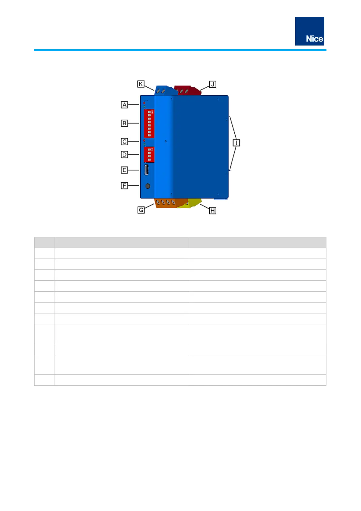
3.2 Device components
Fig.3: Traffic detector LP21/LP22
Loop channel LEDs 1 (red + blue)
Status indicators for the loops and the detector
Basic settings for the detector
Loop channel LEDs 2 (red + blue)
Status indicators for the loops and the detector
DIP switch 2 (LP22 variant)
Basic settings for the detector
Factory settings or fresh adjustment
Connections for induction loops
Output 1 terminal block:
• Relay output 1 (yellow)
Signal outputs for controller
Mounting device for TS35 DIN rail
Output 2 terminal block:
• Relay output 2 (red)
Signal outputs for controller
Connections for power supply
Tab.1: LP21/LP22 Traffic Detector
 Loading...