Pag. 19 a 37
LP21/LP22 Installation instructions en Sensors
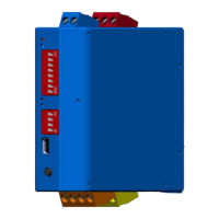
LED position
The LEDs for the loop channel 1 are located at the top or side of the device, for loop channel 2 are in the
middle.
Switch-on threshold for signal output when the loop is covered
Frequency of the loop resonant circuit in two levels
Hold Time until readjustment
Maximum duration of the output signal until automatic frequency
adjustment of the loop channel
Switching between continuous signal and pulse signal at output 2
Time of output signal for activated pulse signal on output 2
Reversing the switching logic for the output signals (inversion)
Switching between presence and direction detection for both outputs
(2 channel variant LP22)
Evaluation logic of the direction of travel when loop is covered according
to the specific application (read the operating instructions!)
Tab.7: Description of the settings
8.2.1 DIP switch assignment of the LP21 variants
The single-channel variants have an 8-pole DIP switch for configuring the detector.
Hold time until readjustment
Output signal 1 inversion
Output signal 2 inversion
Tab.8: DIP switch assignment (default)
 Loading...