4
This control unit for the automation of gates and doors enables control of two gearmotors with single-phase alternating current.
TheunitfeaturesaseriesofDip-switches(miniswitches)thatenabletheselectionofthevariousfunctions,aswellastrimmersusedfor
making adjustments.
The status of the inputs is signalled by LED’s located next to the inputs. An additional LED located near the microprocessor indicates whether
the internal logic is operating properly.
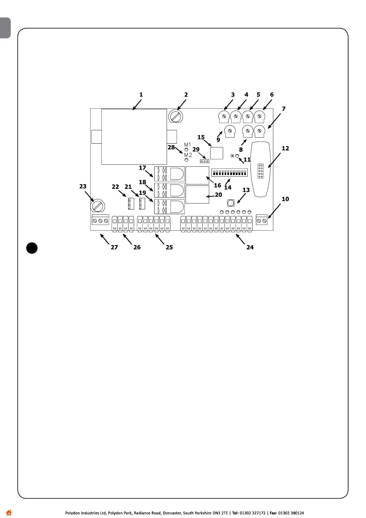
Tofacilitatepartidentication,Fig.1belowshowsthemostsignicantcomponents.
1 Transformer
2 Lowvoltagefuse(500mAF)
3 Forceadjustmenttrimmer(F)
4 PauseTimeadjustmenttrimmer(TP)
5 OpeningTimeDelayadjustmenttrimmer(TRA)
6 Motor1WorkingTimeadjustmenttrimmer(TL1)
7 Motor2WorkingTimeadjustmenttrimmer(TL2)
8 ClosingTimeDelayadjustmenttrimmer(TRC)
9 Manoeuvrebalancetrimmer(BAL)
10 Terminal board for aerial
11 LedOK
12 Radio slot connector
13 Step-by-step button
14 Function selection Dip-Switch
15 Microprocessor
16 Electric lock relay
17 Common motor relay
18 Courtesy light relay
19 Open / Close movement direction relay
20 Phototest relayt
21 Motor 2 Triac
22 Motor 1 Triac
23 Rapidfuse(5A230Vac)or(6.3A120Vac)power
24 Input / output control terminal board
25 Motor outputs terminal board
26 Flashing / C.tsy light output terminal board
27 Power supply terminal board
28 Motors ON LED
29 Jumperforselectionofdecelerationmode(M-RAL)
2) Product description
1
EN

 Loading...


