12
Led Function Description
L1 Automatic Closing
This function causes the gate to close automatically after the programmed time has lapsed. The factory set
Pause Time is 30 seconds, but can be changed to 5, 15, 30, 45, 60 or 80 seconds. If the function is inactive,
functioning will be “semi-automatic”.
L2 Close After Photo This function enables the gate to be kept open for the necessary transit time only. In fact the “Photo”
always causes an automatic closure with a pause time of 5s (regardless of the programmed value).
The action changes depending on whether the “Automatic closing” function is active or not.
When “Automatic Closing” is inactive: The gate always arrives to the totally open position (even if
the Photo disengages first). Automatic closing with a pause of 5s occurs when the Photo is disengaged.
When “Automatic Closing” is active: The opening manoeuvre stops immediately after the
photocells have disengaged. After 5 seconds, the gate will begin to close automatically.
The “Close after photo” function is always disabled in manoeuvres interrupted by a Stop command.
If the “Close after photo” function is inactive the pause time is that which has been programmed or there
is no automatic closing if the function is inactive. .
L3 Always Close The “Always Close” function will trigger, and the gate will close if an open gate is detected when the
power supply returns. A light will flash for 5 seconds before the manoeuvre starts for reasons of safety. If
the function is inactive when the power supply returns, the gate will remain still.
L4 Stand-By This function enables the user to lower consumption to a very minimum. It is particularly useful in cases
when the buffer battery is being used. If this function is active, the control unit will switch the BLUEBUS
output (and consequently the devices) and all the LEDs off one minute after the end of the manoeuvre.
The only LED which will remain on is the BLUEBUS LED which will simply flash more slowly. When a
command arrives, the control unit will reset to complete functioning. If this function is inactive, there will
be no reduction in the consumption.
L5 Peak If this function is activated, the gradual acceleration at the beginning of each manoeuvre will be
disconnected. It enables the peak thrust and is useful whenever static friction is high, e.g. if snow or ice
are blocking the leaf. If the thrust is inactive, the manoeuvre will start with a gradual acceleration.
L6 Pre-flashing With the pre-flashing function, a 3 second pause is added between the flashing light switching on and
the beginning of the manoeuvre in order to warn the user, in advance, of a potentially dangerous
situation. If pre-flashing is inactive, the flashing light will switch on when the manoeuvre starts.
During the normal functioning of the ROBUS350, LEDs L1….L6 will either be on or off depending on the state of the function they
represent. For example, L1 will be on if the “Automatic Closing” function is active.
Programming, personalisation and how to look for and deal with faults on the ROBUS350 will be dealt with in this chapter.
7) Additional information
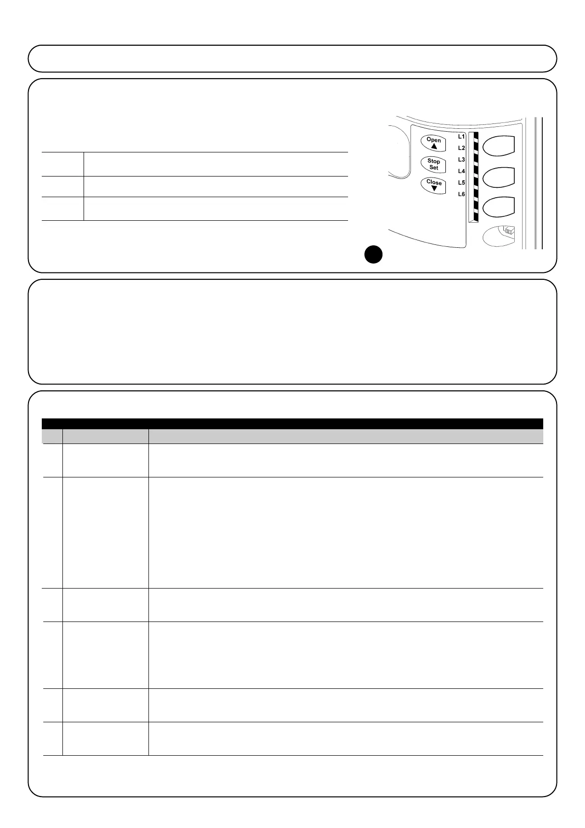
Open The “OPEN” key enables the user to control the opening of the gate or move
▲ the programming point upwards.
Stop The “STOP” key enables the user to stop the manoeuvre. If pressed down for
Set more than 5 seconds it enables the user to enter programming.
Close The “CLOSE” key enables the user to control the closing of the gate or move
▼ the programming point downwards.
7.1) Programming keys
The ROBUS350 control unit feature three keys that can be used to
command the control unit both during tests and programming.
7.2) Programming
A number of programmable functions are available on the
ROBUS350 control unit. The functions are adjusted using 3 keys set
on the control unit: [▲] [Set] [▼] and are used by means of 6 LEDs:
L1…L6
The programmable functions available on ROBUS350 are set out on
2 levels:
Level one: the functions can be adjusted in modes ON-OFF (active
or inactive). In this case, each of the LEDs L1…L6 indicates a func-
tion. If the LED is on, the function is active, if off the function is inac-
tive. See Table 12
Level two: the parameters can be adjusted on a scale of values
(from 1 to 6). In this case, each of the LEDs L1…L6 indicates the
value set (there are 6 possible settings). Please refer to Table 14.
Table 12: list of programmable functions: Level one
7.2.1) Level one functions (ON-OFF functions).
21
 Loading...