8
As soon as ROBUS350 is energized, you should check the following:
1.Make sure that the “BLUEBUS” LED flashes regularly, with about
one flash per second
2.Make sure that the LED’s on the photocells flash (both on TX and
RX); the type of flashing is not important as it depends on other
factors.
3.Make sure that the flashing light connected to the FLASH output
and the lamp LED connected to the “Open Gate Indicator” output
are off.
If the above conditions are not satisfied, you should immediately
switch off the power supply to the control unit and check the electri-
cal connections more carefully. Please refer to Chapter “7.6 Trou-
bleshooting” for further information about finding and analysing fail-
ures.
4.2) Power Supply Connection
The connection of ROBUS350 to the mains must be made by qualified and experienced personnel in possession of the necessary requi-
sites and in full respect of the laws, provisions and standards currently in force.
4.3) Recognition of the devices
After connecting up the power supply, the control unit must be made
to recognise the devices connected up to the BLUEBUS and STOP
inputs. Before this phase, LEDs L1 and L2 will flash to indicate that
recognition of the devices must be carried out.
The connected devices recognition stage can be repeated at any time,
even after installation, e.g. if another device is added. Please refer to
Paragraph “7.3.4 Recognition of other devices” for information about
how to carry out another recognition process.
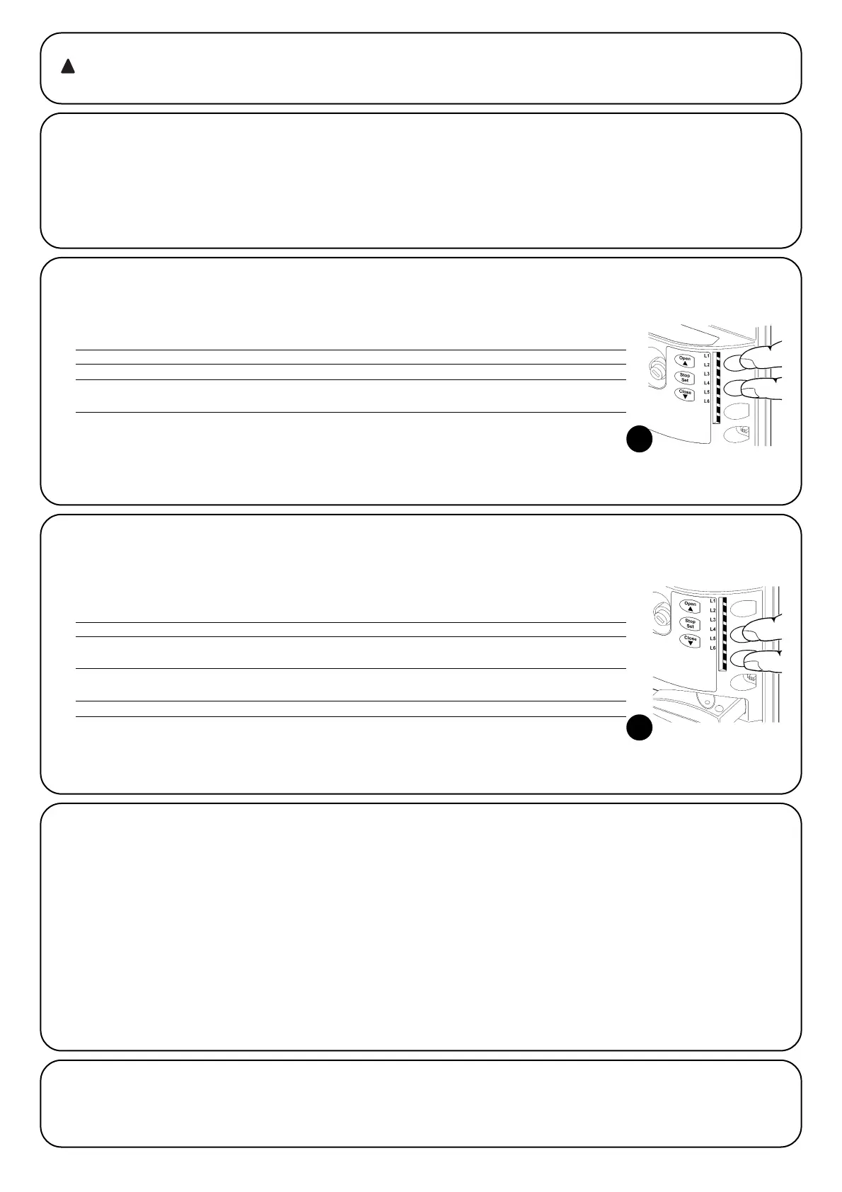
1. Press keys [▲] and [Set] and keep them pressed down
2. Release the keys then LEDs L1 and L2 start flashing rapidly (after approx. 3 sec.)
3. Wait for a few seconds for the control unit to finish recognising the devices
4. STOP LED must remain on when the recognitions stage has been completed, while LEDs L1 and L2 will switch
off (LEDs L3 and L4 will eventually start flashing).
4.4) Recognizing the length of the leaf
After recognizing the devices, LEDs L3 and L4 will start flashing. This
means that the control unit must be made to recognize the length of
the leaf. During this stage, the length of the leaf is measured from the
closing limit switch to the opening limit switch. This measurement is
required to calculate the deceleration points and the partial opening
point.
If the above conditions are not satisfied, you should immediately
switch off the power supply to the control unit and check the electri-
cal connections more carefully. Please refer to Paragraph “7.6 Trou-
bleshooting” for further information.
1. Press keys [▼] and [Set] and keep them pressed down.
2. Release the keys when the manoeuvre starts (after approx. 3 s)
3. Check the manoeuvre in progress is an opening manoeuvre. Otherwise, press the [Stop] key and carefully
check Paragraph “4.1 Choosing the Direction”, then repeat the process from Point 1.
4. Wait for the control unit to open the gate until it reaches the opening limit switch. The closing manouvre wil
start immediately afterwards.
5. Wait for the control unit to close the gate.
4.5) Checking gate movements
On completion of the recognition of the length of the leaf, it is advis-
able to carry out a number of manoeuvres in order to check the gate
travels properly.
1.Press the [Open] key to open the gate. Check that gate opening
occurs regularly, without any variations in speed. The leaf must
only slowdown and stop when it is between 70 and 50 cm from
the opening mechanical stop. Then, at 2÷3cm from the mechan-
ical opening stop the limit switch will trigger.
2.Press the [Close] key to close the gate. Check that the gate clos-
es regularly without any variations in speed. The leaf must only
slowdown and stop when it is between 70 and 50 cm from the
closing mechanical stop. Then, at 2÷3cm from the mechanical
closing stop the limit switch will trigger.
3.During the manoeuvre, check that the flashing light flashes at a
speed of 0.5 seconds on and 0.5 seconds off. If present, also
check the flashes of the light connected to the S.C.A. terminal:
slow flashes during opening, quick flashes during closing.
4.Open and close the gate several times to make sure that there are
neither points of excessive friction nor defects in the assembly or
adjustments.
5. Check that the fastening of the ROBUS350 gearmotor, the rack
and the limit switch brackets are solid, stable and suitably
resistent, even if the gate accelerates or decelerates sharply.
4.6) Preset functions
The ROBUS350 control unit has a number of programmable functions.
These functions are set to a configuration which should satisfy most
automations. However, the functions can be altered at any time by
means of a special programming procedure. Please refer to paragraph
“7.2 Programming” for further information about this.
18
19
 Loading...