6
3.3) Installation of the Various Devices
If other devices are needed, install them following the directions provided in the corresponding instructions. Check this in paragraph “3.5
Description of electrical connections” and the devices which can be connected to the ROBUS350 in Figure 2.
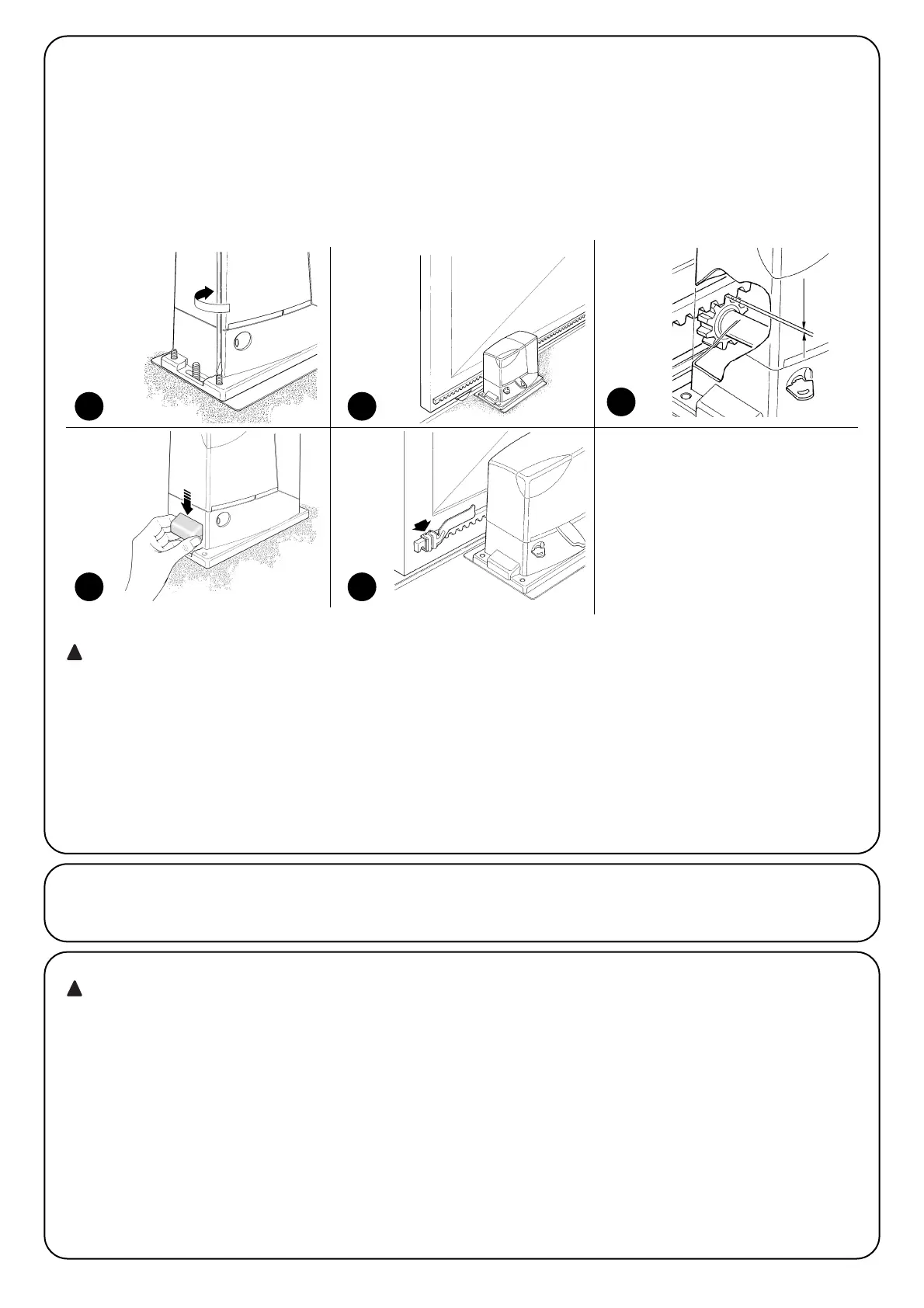
in order to prevent the weight of the leaf from affecting
the gearmotor, it is important that there is a play of 1÷2mm
between the rack and the pinion as shown in Figure 10.
8. Slide the leaf, using the pinion as a reference point for the fas-
tening the other elements of the rack.
9. Cut away any excess of the rack.
10. Open and close the gate several times and make sure that the
rack is aligned with the pinion with a maximum tolerance of 5mm.
Moreover, check that the play of 1÷2mm has been respected
along the entire length between the pinion and the rack.
11.Thoroughly tighten the two fixing nuts of the gearmotor, making
sure it is well fastened to the ground. Cover the fixing nuts with
the relative caps as shown in figure 11.
12.Fix the two “Opening” and “Closing” limit switch brackets with the
relative dowels to the outer sides of the rack as shown in Figure
12. Consider that the leaf will slide for about another 2÷3cm after
the limit switch cuts in. The brackets should be positioned at a
sufficient distance from the mechanical stops.
13.Lock the gearmotor as shown in the “Release and manual move-
ment” paragraph in the Chapter “Instructions and Warnings for
Users of the ROBUS gearmotor”
8 9
10
11 12
If the rack is already present, once the gearmotor has been fastened
use the adjustment dowels as shown in Figure 8 to set the pinion of
ROBUS350 to the right height, leaving 1÷2mm of play from the rack.
Otherwise, the installer must carry out the following procedure in
order to fasten the rack:
6.Release the gearmotor as shown in the “Release and manual
movement” paragraph in the Chapter “Instructions and Warnings
for users of the ROBUS gearmotor”
7.Open the leaf up completely and place the first piece of the rack
on the pinion. Check that the beginning of the rack corresponds
to the beginning of the leaf, as shown in Figure 9. Leave a 1÷2mm
play between the rack and the pinion, then fasten the rack to the
leaf using suitable means.
1÷2
3.4) Electrical connections
only carry out electrical connections once the electric-
ity supply to the system has been switched off. Discon-
nect any buffer batteries present.
1. Remove the protection cover in order to access the electronic
control unit of the ROBUS350. The side screw must be removed,
and the cover lifted upwards.
2. Remove the rubber membrane which closes the hole for passage
of the cables and insert all the connection cables towards the var-
ious devices, leaving a length of 20÷30cm longer than necessary.
See Table 3 for information regarding the type of cables and Fig-
ure 2 for the connections.
3. Use a clamp to collect together and join the cables which enter
the gearmotor. Place the clamp just underneath the hole the
cables enter through. Make a hole in the rubber membrane which
is slightly smaller than the diameter of the cables which have been
collected together, and insert the membrane along the cables until
you reach the clamp. Then put the membrane back in the slot of
the hole the cables pass through. Lay a second clamp for col-
lecting the cables which are set just above the membrane.
4. Connect the power cable to the appropriate terminal as shown in
Figure 13, then block the cable at the first cable block ring using
the clamp.
5. Connect up the other cables according to the diagram in Figure
15. The terminals can be removed in order to make this work eas-
ier.
6. Once the connections have been completed, block the cables
collected in the second cable block ring using clamps. The
excess of the antenna cable must be blocked to the other cables
using another clamp as shown in Figure 14.
 Loading...