16
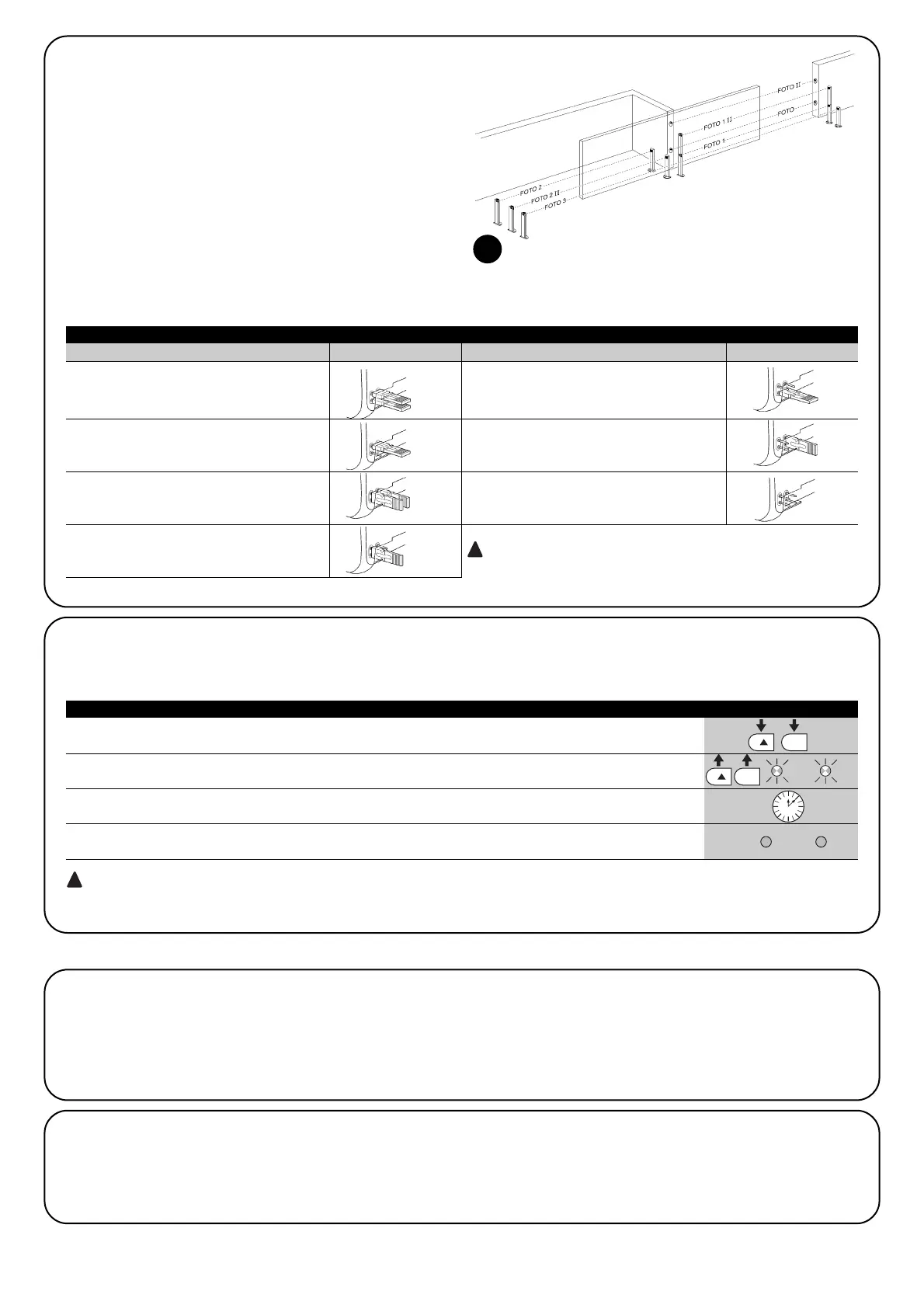
FOTO
External photocell h=50cm;
activated when gate closes
FOTO II
External photocell h=100cm;
activated when gate closes
FOTO 1
Internal photocell h=50;
activated when gate closes
FOTO 1 II
Internal photocell h=100;
activated when gate closes
FOTO 2
External photocell
activated when gate opens
FOTO 2 II
Internal photocell
activated when gate opens
FOTO 3
Single photocell for the entire
automation system
In the case of the installation of FOTO 3 and FOTO II together
the position of the photocell elements (TX-RX) must comply with the
provisions contained in the photocell instruction manual
7.3.3) Photocells
By means of addressing using special jumpers, the “BlueBUS” sys-
tem enables the user to make the control unit recognise the photo-
cells and assign them with a correct detection function.
The addressing operation must be done both on TX and RX (setting
the jumpers in the same way) making sure there are no other cou-
ples of photocells with the same address. In an automation for slid-
ing gates, with ROBUS350 it is possible to install the photocells as
shown in Figure 22.
After the installation or removal of photocells, the recognition phase
in the control unit as described in Paragraph “7.3.4 Recognition of
other devices” must be carried out.
22
Table 18: Photocell addressing
Photocell Jumpers Photocell Jumpers
7.3.4) Recognition of other devices
Normally the recognition of the devices connected to the BlueBUS and the STOP input takes place during the installation stage. However, if
new devices are added or old ones removed, the recognition process can be gone through again by proceeding as follows:
1. Press keys [▲] and [Set] and hold them down
2. Release the keys when L1 and L2 LED’s start flashing very quickly (after approx. 3 s)
L1 L2
3. Wait a few seconds for the control unit to finish recognizing the devices
4. When the recognition stage is completed L1 and L2 LED’s will go off, the STOP LED must remain on,
while L2…L6 LED’s will light up according to the status of the relative ON-OFF functions L1 L2
After you have added or removed any devices, the automation system must be tested again according to the directions
contained in paragraph 5.1 “Testing”.
Table 19: Recognition of Other Devices Example
7.4.1) “Always open” Function
The “Always open” function is a control unit feature which enables
the user to control an opening manoeuvre when the “Step-by-Step”
command lasts longer than 2 seconds. This is useful for connecting
a timer contact to the “Step-by-Step” terminal in order to keep the
gate open for a certain length of time, for example.
This feature is valid with any kind of “Step-by-Step” input program-
ming, except for “Close”. Please refer to the “Step-by-Step Func-
tion” parameter in Table 14.
7.4.2) “Move anyway” function
In the event that one of the safety devices is not functioning proper-
ly or is out of use, it is still possible to command and move the gate
in “Man present” mode. Please refer to the Paragraph “Control with
safety devices out of order” in the enclosure “Instructions and Warn-
ings for users of the ROBUS gearmotor” for further information.
7.4) Special Functions
 Loading...