ENGLISH – 27
Table 17
SMXI / SMXIS
Receiver output Command
Output No. 1 “Step-by-Step”
Output No. 2 “Partial opening”
Output No. 3 “Open”
Output No. 4 “Close”
If the OXI radio receiver used in “EXTENDED MODE” is installed, it
may send the commands shown in “Table 18“.
Table 18
OXI / OXIFM /OXIT / OXITFM IN MODE 2 EXTENDED
No. Command Description
1 Step-by-Step “SbS” (Step-by-Step) command
2 Partial opening 1 “Partial opening 1” command
3 Open “Open” command
4 Close “Close” command
5 Stop Stops the manoeuvre
6
Condominium
Step-by-Step
Command in condominium mode
7
High priority Step-
by-Step
Commands also with the automation
locked or the commands enabled
8 Partial open 2
Partial opening (the M2 gate leaf
opens to 1/2 the full length)
9 Partial open 3
Partial open (the two gate leaves open
to 1/2 the full length)
10
Opens and locks
the automation
Triggers an opening manoeuvre
and, once this terminates, locks the
automation; the control unit will not
accept any command other than “High
priority Step-by-Step” and automation
“Unlock”, or (only from Oview) the
following commands: “Unlock and
close” and “Unlock and open”
11
Closes and locks
the automation
Triggers a closing manoeuvre and,
once this terminates, locks the
automation; the control unit will not
accept any command other than “High
priority Step-by-Step” and automation
“Unlock”, or (only from Oview) the
following commands: “Unlock and
close” and “Unlock and open”
12 Lock automation
Triggers the stoppage of the
manoeuvre and locks the automation;
the control unit will not accept any
command other than “High priority
Step-by-Step” and automation
“Unlock”, or (only from Oview) the
following commands: “Unlock and
close” and “Unlock and open”
13
Release
automation
Triggers unlocking of the automation
and restores normal operation
14
On Timer
Courtesy light
The courtesy light output switches on
with timer-based switching off
15
On-Off
Courtesy light
The courtesy light output switches on
and off in Step-by-step mode
l
For further information, consult the specic manual
of the receiver.
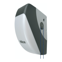
9.4 CONNECTING AND INSTALLING THE BACK-
UP BATTERY
f
The electrical connection of the battery to the con-
trol unit must be made only after completing all the
installation and programming stages, as the battery
is an emergency power supply.
To install and connect the battery:
1. remove the plastic protection (A) with the aid of a screwdriver
32
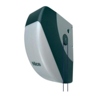
2. connect the appropriate cable to the back-up battery con-
nector
33
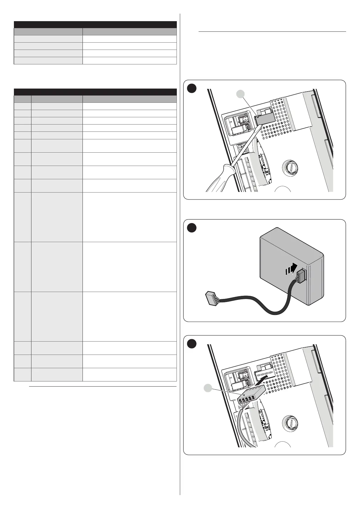
3. insert the relative connector (C) on the control unit
C
34
 Loading...