ENGLISH – 9
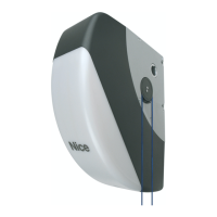
3.7 MANUALLY UNLOCKING AND LOCKING THE
GEARMOTOR
The gearmotor is equipped with a mechanical unlocking device
that can be used to open and close the door manually.
These manual operations should only be performed in case of a
power outage, malfunctions or during the installation phases.
To unlock the device:
1. pull the ball (A)
2. the door can now be moved manually to the desired posi-
tion.
A
B
10
To lock the mechanism, pull the ball (B).
ELECTRICAL CONNECTIONS
4
4 ELECTRICAL CONNECTIONS
4.1 PRELIMINARY CHECKS
f
All electrical connections must be made with the
system disconnected from the mains electricity and
with the back-up battery (if present) disconnected.
a
The connection operations must only be carried out
by qualied personnel.
To make the electrical connections:
1. take out the screw and remove the protective cover (A) by
lifting it up
A
11
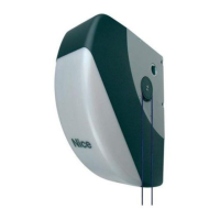
2. insert all the connecting cables into the various devices,
leaving them 8÷12 in (20÷30 cm) longer than necessary. Re-
fer to “Table 4” for the type of cables and to “Figure Table
4” for the connections.
3. use a clamp to hold together all the cables entering the gear-
motor then place the clamp slightly below the cable entry
hole
4. connect the other cables according to the diagram shown
in “Figure 12”. For greater convenience, the terminals are
removable.
12
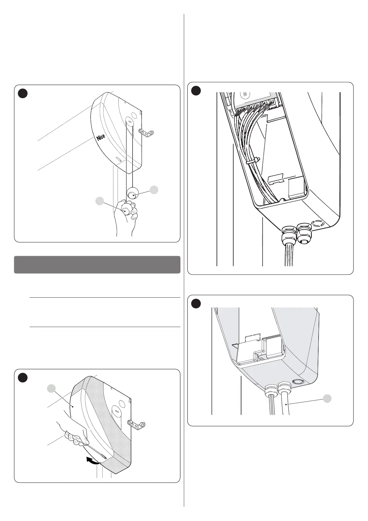
5. Connect the power cable (B) to the relevant socket, then use
another clamp to fasten the cable onto the rst cable ring.
B
13
 Loading...