VBA10401-R.3623.A
- A18 ・ -
・
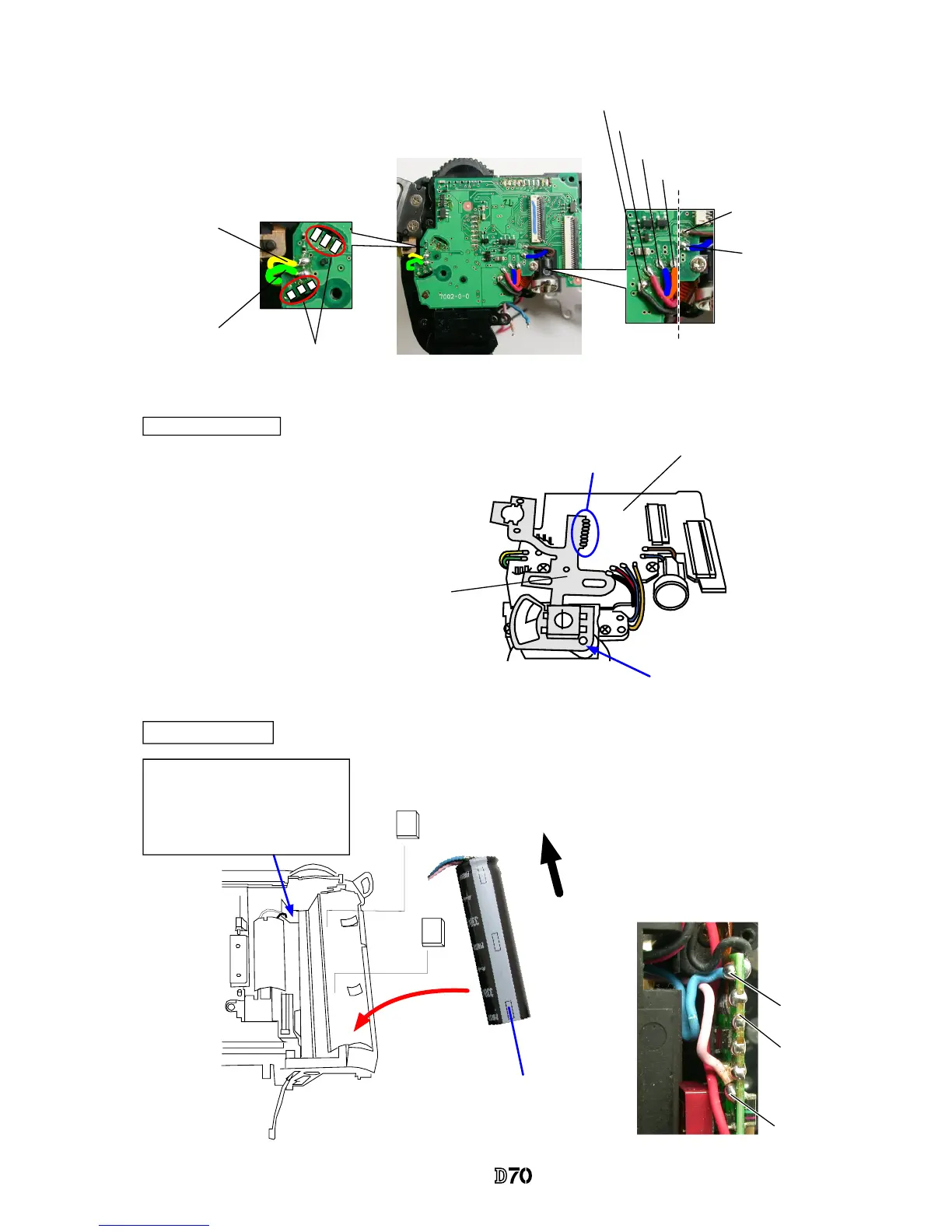
Make soldering bridges on the sub-PCB (#B1002)
and solder 8 wires.
Soldering bridges
Yellow
Green
Main SW FPC
Soldering bridges
Positioning pin
#B1002
#B1011
・
Attach the main SW FPC (#B1011) on the
sub-PCB (#B1002), and make soldering
bridges of them.
Note: Do NOT let 4 wires (black, red, blue,
and orange) be on the right side of the
dotted line by exceeding it.
Main condenser
Pass 2 wires (pink and blue) through
this hole of the main condenser
(#1043) to come out to the front side
of the rear body.
Direction for
positioning
Attach with the polarity
identication mark
upwards.
#754×2
Solder 2 wires (pink and blue) on
the front SB PCB of the rear body.
SB PCB
Blue
Pink
Black
Red
Blue
Orange
Blue
Brown
#1043
:
Identication
SW
:
Identication SW
:
AF assist
illuminator
:
SQ motor
:
SQ motor
:SB-PCB
:SB-PCB
:Main
condenser
:
AF assist
illuminator
:Main
condenser
 Loading...