FSA03601-R.3629.A
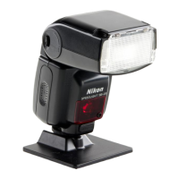
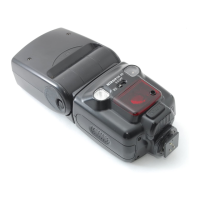
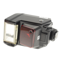
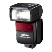
- A3・SB-600 -
#72
・
By handling the above spring (#60) and
zoom pressure shaft (#58) with care,
assemble the lighting unit and motor unit.
・
Insert the guide shaft (#68) in the direction
indicated by the arrow, and attach the
E-ring (#72).
・
Apply the screw lock (EDB0011) a little
on the contact part of the E-ring and
guide shaft.
・
Pass the gray wire of the Xe-A PCB
through under the Xe band (#54).
#70
#222×2
#227×2
#67
A
B
・
First, put the A part of the zoom shaft (#67)
into the hole of the motor holder (#69),
then push the B part of it into #69.
・
Solder 2 wires on the ZOOM motor.
#69
#96
#58
#60
#59
Hook
Hook
・
Insert the zoom pressure shaft holder (#59) into the
lighting unit, and x the 2 hooks as shown left.
・
Insert the spring
(
#60) and zoom pressure shaft
(#58).
Lighting unit
Lighting unit
Motor unit
#68
Motor unit
Grease: G7100
Grease: G7100
Adhesive: EDB0011
#54
Xe-A PCB
Gray wire
Grease: G7100
BLUE
PURPLE
#MT1
 Loading...
