 Loading...
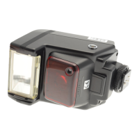
Do you have a question about the Nikon SB-600 FSA03601 and is the answer not in the manual?
| Compatibility | Nikon i-TTL |
|---|---|
| Guide Number | 30 (ISO 100, m, 35mm) |
| Zoom Range | 24-85mm |
| Power Source | 4 x AA batteries |
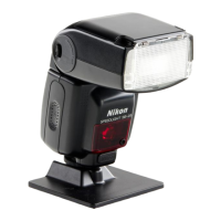
| Type | Shoe mount |
| Flash Modes | TTL, Manual |
| Wireless Mode | Yes |
| Flash Coverage | 24-85mm (14mm with built-in wide panel) |
| Dimensions | 2.7 x 5.0 x 3.5" (68.0 x 126.0 x 89.0mm) |
| Weight | Approx. 350g (without batteries) |