I Name and Function of Each Part
1 System configuration
- 9 -
I
I
Name and Function of Each Part
1
System configuration
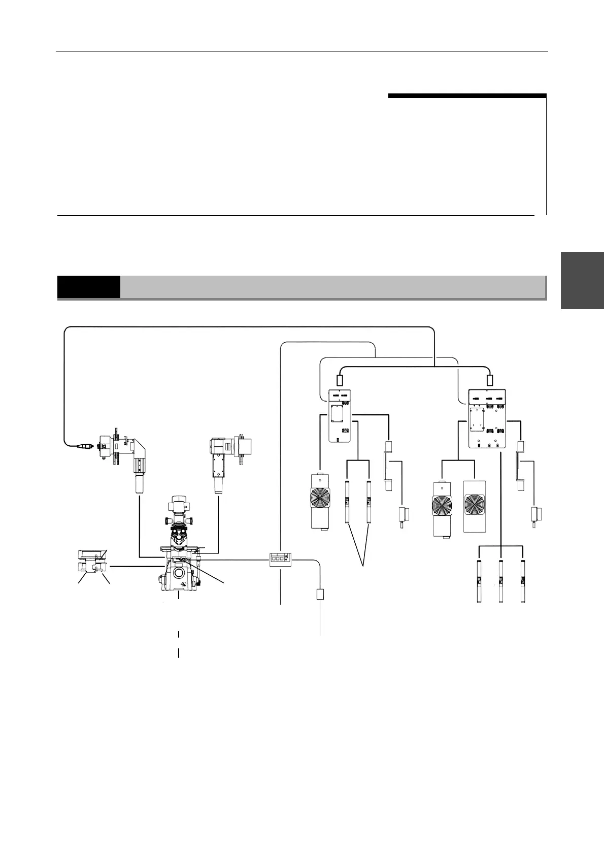
System diagram
(2) TIRF attachment
(3) Optical-fiber cable
(4) Two-lase
unit
(5) Air-cooled argon laser
(model: 161C)
(6) He-Ne laser
(G: 543 nm, Y: 594 nm)
(7) Solid-state laser
(model:
CDPS532M-020)
(8) Solid-state
laser adapter
(9) Shutter
control unit
(10) AC adapter
(13) Connect to
PC serial port
(15) Stage-up kit
(16) Epi-fl cassette holder
(17) Epi-fl attachment
(4) Three-lase
unit
(7) Solid-state lase
(model:
CDPS532M-020)
(6) He-Ne laser
(G: 543 nm, Y: 594 nm, R: 633 nm)
(14) TIRF cassette
holder
(8) Solid-state
laser adapter
(5) Air-cooled
argon laser
(model:
161C, 163)
161C 161C 163
GYR
GY
(18) TV camera
(19) Monitor
(12) Eyepiece
shutter
(11) Power cable
(1) Inverted microscope TE2000-E/ U/ S
The illumination pillar must be moved aside
when the focal point of the laser beam is
adjusted; be sure to use the illumination pillar
T-DH100W.
 Loading...