I Name and Function of Each Part
6 Shutter control unit
- 18 -
6
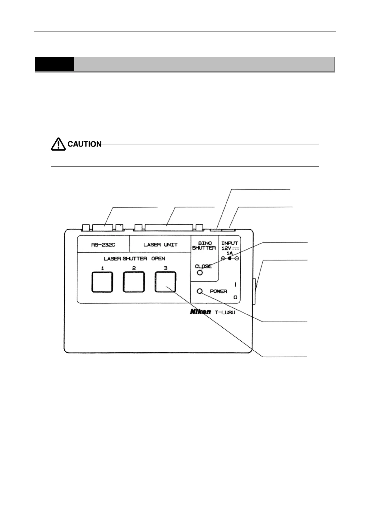
Shutter control unit
This unit is designed to open or close the motorized shutter housed within each laser unit. Although
the unit can open or close up to three channels of motorized shutters, for safety reasons, operation of
motorized shutters is conducted through mutually exclusive control, as a result of which only one
shutter can be opened at a time.
Connect the cables of the AC adapter, the eyepiece shutter, and the laser unit at the locations shown
in the figure.
To prevent malfunctions, always turn off the system power before attaching or detaching any of
the cables.
(1) Power switch
Turns the 12 VDC power from the AC adapter on or off.
(2) Power lamp
Lights green when the power is on.
(3) AC adapter connector
Connects the AC adapter output.
(4) Eyepiece shutter connector
Connects the microscope-mounted eyepiece shutter connector.
(1) Power switch
(2) Power lamp
(8) Shutter switch
(3) AC adapter
connector
(4) Eyepiece shutter
connector
(6) Laser unit
connector
(7) Serial IF
connector
(5) Eyepiece
shutter closed
lamp
 Loading...