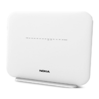
Table 4-4, “G-2425G-B indoor ONT physical connections” (p. 48) describes the physical
connections for G-2425G-B indoor ONTs.
Table 4-4 G-2425G-B indoor ONT physical connections
Connection
1
Print Letters Description
POTS port TEL1 and TEL2 This connection is provided through an RJ-11 port. One POTS connection is supported.The
POTS port supports voice services.
Ethernet ports LAN1 to LAN4 This connection is provided through Ethernet RJ-45 connectors. Up to four 10/100/1000
Base-T Ethernet interfaces are supported.The Ethernet ports can support both data and
in-band video services on all four interfaces.
Power input POWER This connection is provided through the power connector. A power cable fitted with a barrel
connector is used to make the connection.
Reset button RESET Pressing the Reset button for less than 10 seconds reboots the ONT; pressing the Reset
button for 10 seconds resets the ONT to the factory defaults, except for the LOID and SLID.
WLAN button WLAN Wi-Fi service is compliant with IEEE 802.11 standards and is enabled and disabled using the
WLAN button.
WPS button WPS The Wi-Fi Protected Setup (WPS) button enables and disables the WPS.
LED button LED The LED button turns the LED indicators on or off.
On/Off button ON/OFF This button turns the ONT on or off.
USB port USB1 and USB2 This connection is provided through 1 USB port on the side of the ONT. The ONT supports
external USB hard drives that can be made accessible to all LAN devices.
Fiber optic port The SC/APC fiber optic port is located at the back of the ONT and provides the connection for
the fiber optic cable.
Notes:
1. The primary path for the earth ground for these ONTs is provided by the 12V Return signal in the power
connector.
4.6 G-2425G-B LEDs
Figure 4-4, “G-2425G-B indoor ONT LEDs” (p. 50) shows the G-2425G-B indoor ONT LEDs.
G-2425G-B unit data sheet
G-2425G-B LEDs
7368 ISAM ONT
Draft Draft
August 2020
Issue 4 49
Nokia – Proprietary and Confidential
Use pursuant to applicable agreements
3FE-48293-ACAA-TCZZA

 Loading...