SIM interface
The SIM interface is programmed to support 3V and 1.8V SIMs.
The SIM interface is the electrical interface between the Subscriber Identity Module Card (SIM Card) and mobile
phone.
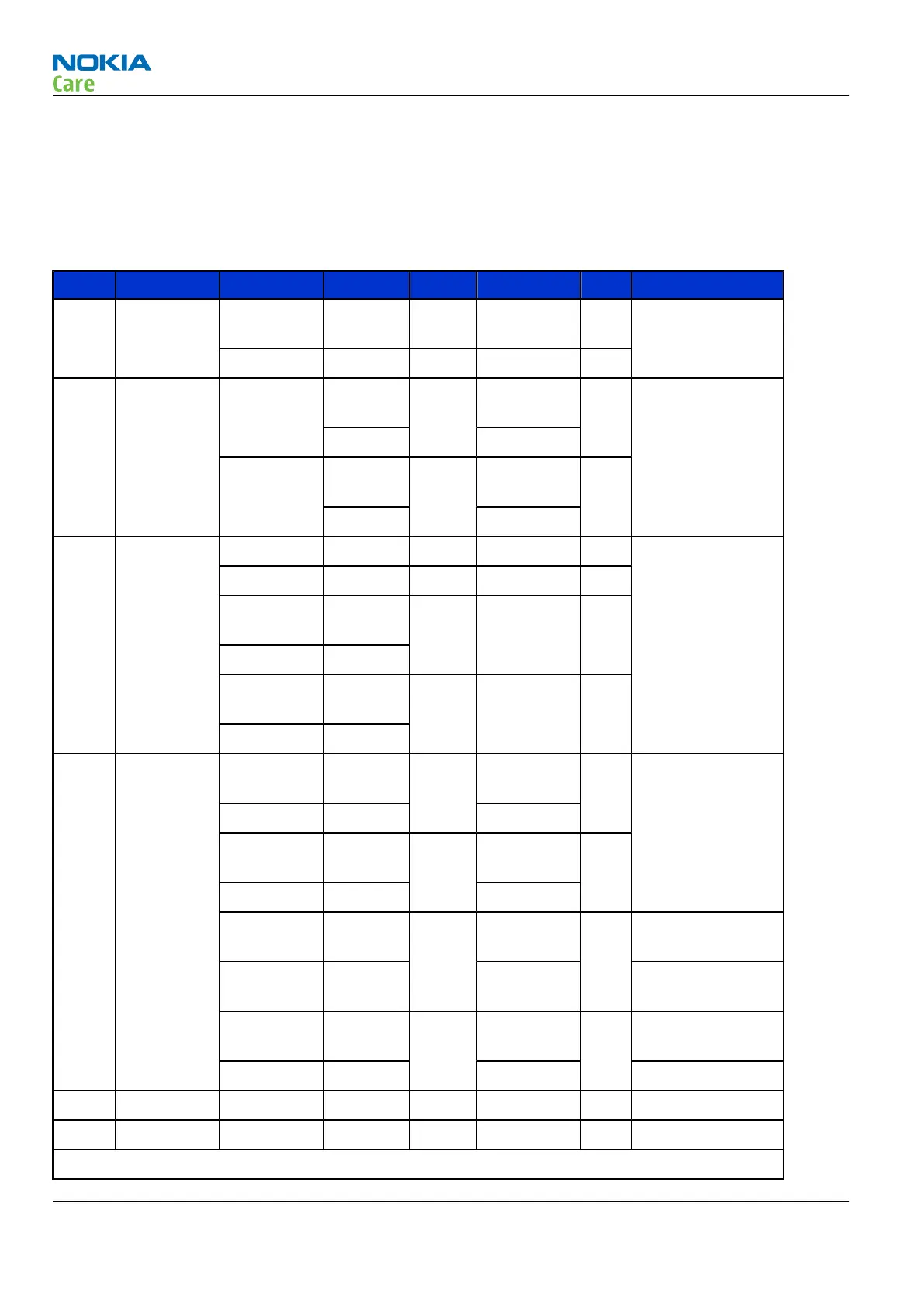
Table 8 SIM interface
Pin Name Parameter Min Typ Max Unit Notes
1 VSIM 1.8V SIM
Card
1.6 1.8 1.9 V Supply voltage
3V SIM Card 2.8 3.0 3.2 V
2 SIMRST 1.8V SIM
Card
0.9xVSI
M
VSIM V SIM reset (output)
0 0.15xVSIM
3V SIM Card 0.9xVSI
M
VSIM V
0 0.15xVSIM
3 SIMCLK Frequency 3.25 MHz
Trise/Tfall 50 ns
1.8V Voh 0.9xVSI
M
VSIM V
1.8V Vol 0
3V Voh 0.9xVSI
M
VSIM V
3V Vol 0
4 DATA 1.8V Voh 0.9xVSI
M
VSIM V SIM data (output)
1.8V Vol 0 0.15xVSIM
3V Voh 0.9xVSI
M
VSIM
3V Vol 0 0.15xVSIM
1.8V Vih 0.7xVSI
M
VSIM V SIM data (input)
1.8V Vil 0 0.15xVSIM Trise/Tfall max
1us
3V Vil 0.7xVSI
M
VSIM
3V Vil 0 0.15xVSIM
5 NC Not connected
6 GND GND 0 0 V Ground
VSIM specified in regulator section in this document
RH-99; RH-100; RH-105; RH-106
System module
Page 6 –12 COMPANY CONFIDENTIAL Issue 2
Copyright © 2007 Nokia. All rights reserved.

 Loading...