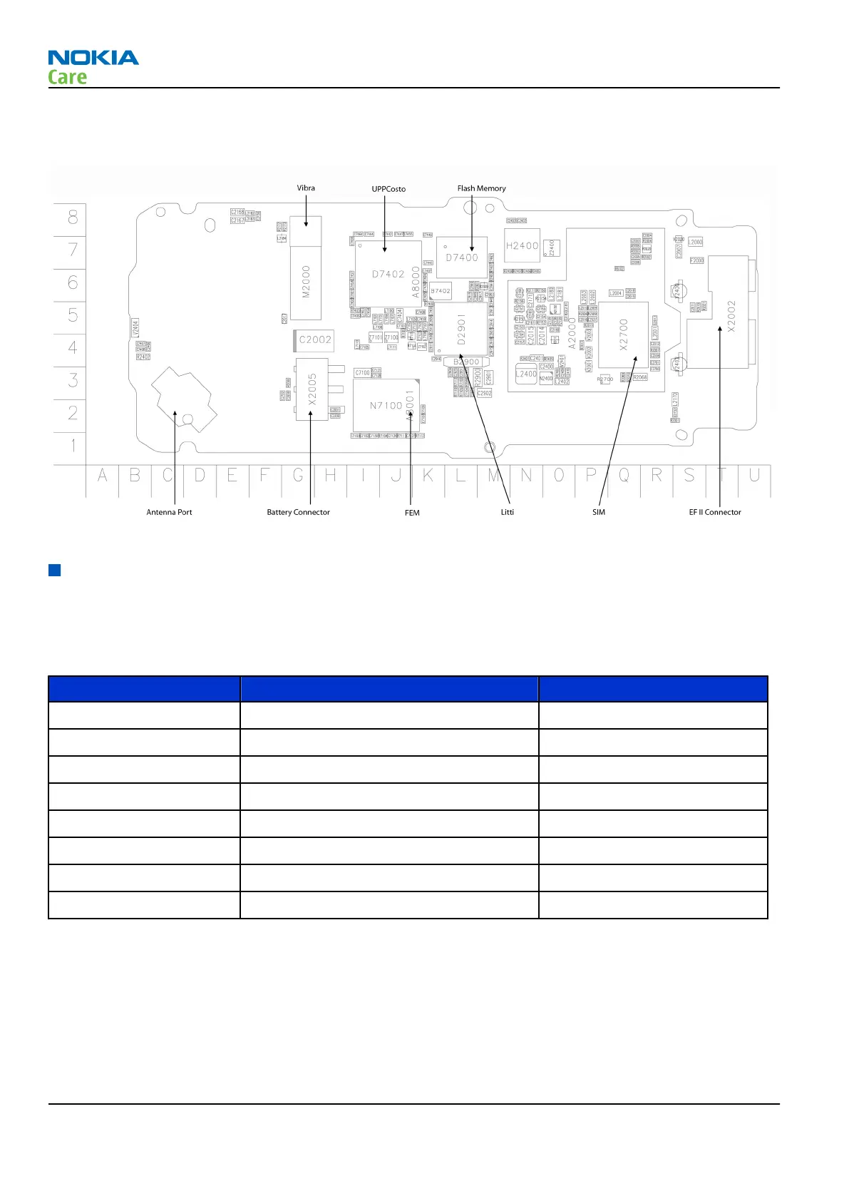
PWB outline
Figure 84 PWB top side component placement
RF description
Frequency band, power and multi-slot class
The requirements leads to the specification in the table below:
Table 10 Frequency bands and TX power class
System Frequency band TX power class
GSM850 Tx: 824 - 849 MHz 4 (33 dBm)
RX: 869 - 894 MHz
GSM900 Tx: 880 – 915 MHz 4 (33dBm)
Rx: 925 – 960 MHz
GSM1800 Tx: 1710 – 1785 MHz 1 (30dBm)
Rx: 1805 – 1880 MHz
GSM1900 Tx: 1850 - 1910 MHz 1 (30 dBm)
Rx: 1930 - 1990 MHz
Transmitter Architecture Description
The transmitter in DRP2 is based on the frequency synthesizer with a direct frequency/phase modulation
capability. The frequency synthesizer is implemented as an All Digital PLL (ADPLL), where the FCW is digital
modulated by filtered TX data. The fundamental frequency of the RF oscillator in the ADPLL is running around
3.6GHz, which is divided by 4 or 2 to generate CW frequencies in the lower and upped bands of interest. The
TX data are feed into two points of the ADPLL. The GMSK modulated output signal of the ADPLL block are fed
into Pre-Power Amplifier (PPA) buffer.
RH-99; RH-100; RH-105; RH-106
System module
Page 6 –14 COMPANY CONFIDENTIAL Issue 2
Copyright © 2007 Nokia. All rights reserved.
 Loading...