SFP-400B 15124:G1 06/24/97
15
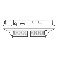
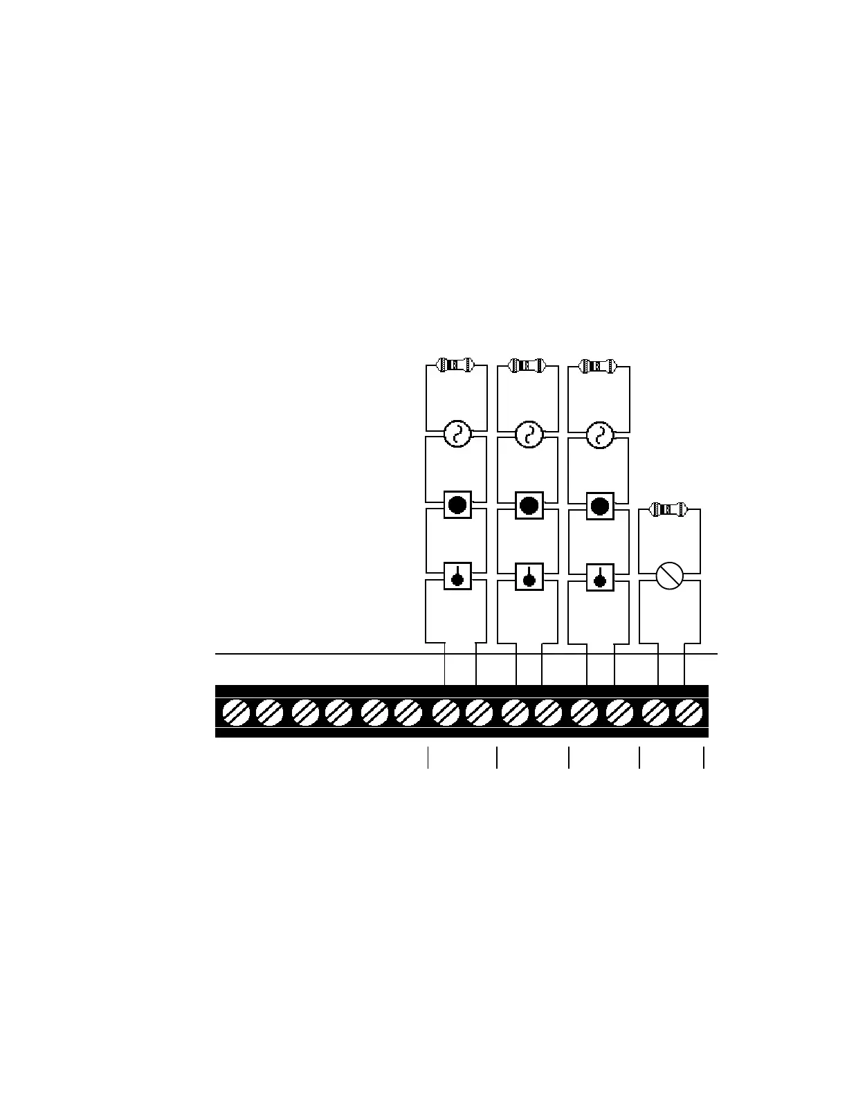
3.2 Initiating Device Circuits
Zones
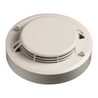
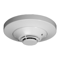
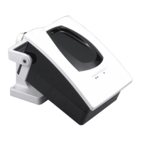
Wire all alarm initiating devices sequentially for proper supervision. Initiating devices include: manual pull
stations, heat, photoelectric, and ionization type detectors; and waterflow alarm devices. Refer to the
Device Compatibility Chart.
Notes:
1) Observe polarity when connecting polarized devices.
2) All circuits are supervised and power limited.
3) Leave Dummy Load (provided) on all unused circuits.
TB4
4.7K, 1/2-Watt
(part # 71252 )
4.7K, 1/2-Watt
(part # 71252 )
4.7K, 1/2-Watt
(part # 71252 )
Normally
Open
Tamper
Switch
+-
+-
+-
+-
Style B
Initiating
Device
Circuit
Style B
Initiating
Device
Circuit
Style B
Initiating
Device
Circuit
Two-wire
Smoke
Detector
Heat Detector
Manual
Pull Station
IN #1 IN #2 IN #3 IN #4
Style B
Supervisory
Circuit
(if SW1 switch
3 is set "ON")
Figure 3.2-1: Example of Initiating Device Circuits
 Loading...