SFP-400B 15124:G1 06/24/97
5
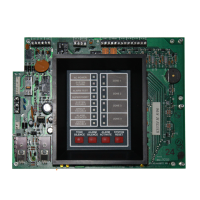
1.0 The SFP-400B
1.2 Circuits
Input Circuits
Initiating Device Circuit 1 (Style B)
Initiating Device Circuit 2 (Style B)
Initiating Device Circuit 3 (Style B)
Initiating Device Circuit 4 (Style B)
Output circuits
Notification Appliance Circuit 1 (Style Y)
Notification Appliance Circuit 2 (Style Y)
Front Panel Control Switches
Switch 1 Tone Silence
Switch 2 Alarm Silence
Switch 3 Alarm Activate
Switch 4 System Reset
1.1 Features
o Microprocessor-controlled.
o Power-limited on all circuits except Municipal
Box Output.
o Alarm and trouble resound.
o Four Style B Initiating Device Circuits.
o Two Style Y Notification Circuits.
o General alarm and trouble relays.
o Optional module for 4 zone relays (4XZM).
o Optional transmitter module (4XTM). Com-
plies with NFPA 72 Auxiliary and Remote
Station Protective Signaling systems.
o Optional supervised remote annunciator
(RZA-4X). Requires LED Interface Module
(4XLM).
o Optional digital communicator (NOTI-FIRE
911A/911AC). Complies with NFPA 72-
1993 Central Station and Remote Station
Protective Signaling systems.
o Waterflow Input Option.
o Supervisory Input Option.
o Complies with NFPA 72 Proprietary Protective
Signaling System (requires Potter EFT-C
McCulloh Transmitter).
o One Man Walk Test.
o Disable/enable controls per Initiating Device
Circuit.
o Last Event Recall.
o Battery/Earth fault supervision.
o Fuse protection on all Notification Appliance
Circuits.
o Unregulated output power, 2.25 amperes.
o 7 AH to 15 AH battery options, up to 90 hours
standby.
o Resettable and non-resettable regulated power
outputs.
o Extensive transient protection.
o Watchdog timer to supervise microprocessor
(includes MICRO FAIL LED).
o Output circuits protected against false activa-
tions.
o Slide-in zone identification labels.
o Steel cabinet 14.5" wide by16" high by 5" deep.
o Dead-front dress panel option (DP-400B).
o Alarm verification option.
 Loading...