SFP-400B 15124:G1 06/24/97
25
a. Two-wire detector heads
b. Four-wire detector heads
c. End of Line Relays
d. Add lines a, b, & c for subtotal
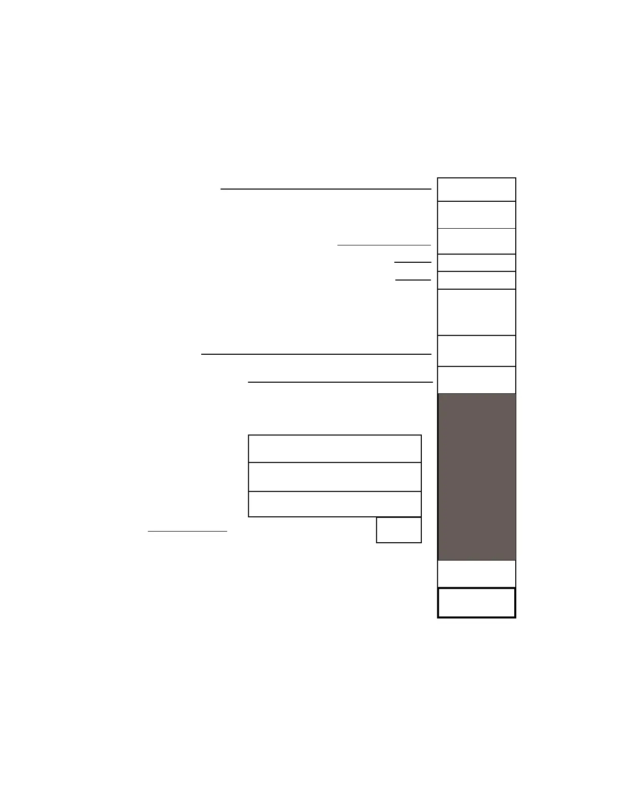
Table A-1: Standby Battery Requirements
The Standby Battery Current figure obtained in Table A - 1 represents the amount of current that must
be supplied by the secondary power source (batteries) to sustain control panel operation for one hour.
Basic Control Panel 80 mA
Control panel with AC power off, System Trouble LED and audible trouble sounder on.
If using a 4XZM Zone Relay Module [ ] X 8 mA =
If using a 4XTM Transmitter Module, add 11 mA
If using the Reverse Polarity Alarm output, add 5 mA
If using the Reverse Polarity Trouble output, add 5 mA
If using a 4XLM/RZA-4X Driver/Annunciator combination:
[ 1 ] X 19 mA =
Auxiliary Power
If using a
911A
, add 30 mA
X=
X=
X 25.0 mA =
Add last column for Standby Battery Current
and continue to Table A-2.
(113 mA for 60 hours of standby)
Place subtotal here :
Total
Current
Number
in use
Device
Current
(see Device Compatibility
Document for data )
Appendix A: Power Calculations
 Loading...