SFP-400B 15124:G1 06/24/97
24
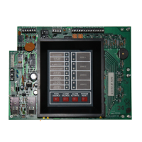
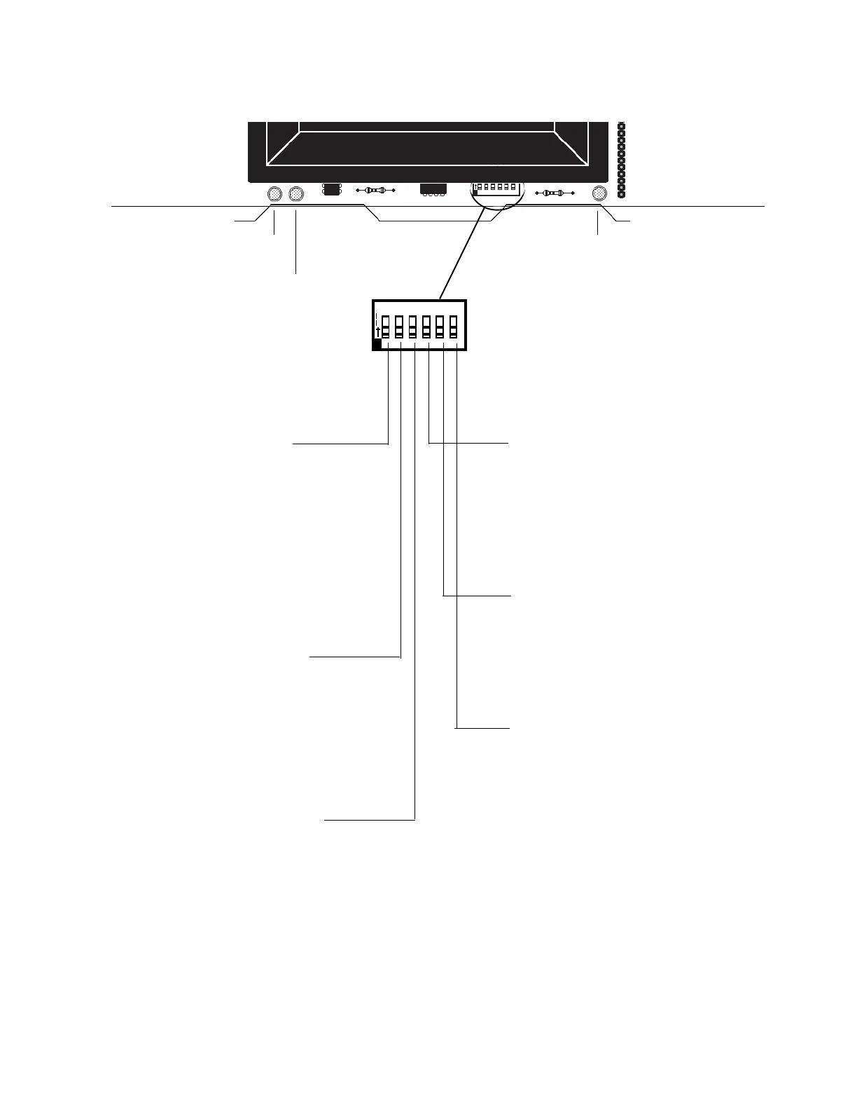
1 2 3 4 5 6
O
N
To set a switch to the "ON" position,
slide it up.
Micro Fail LED
Battery Fail
LED
Ground Fault LED
3.7 Dip Switch Location and Descriptions
Switch 4: Silence Inhibit
If selected and an alarm occurs, the
ALARM SILENCE switch will not func-
tion until 60 seconds have passed since
initiation of the alarm. If another alarm
occurs, the timer will restart at 60 sec-
onds.
Switch 5: Disable Bells
When this switch is set "ON", the four
Indicating Appliance Circuits and the
SYSTEM ALARM relay will be disabled,
and a local trouble signal will be gener-
ated.
Switch 6: One Man Walk Test
Setting this switch to the "ON" position
places the control panel in Walk Test
Mode. The first alarm on Initiating Cir-
cuit under test will ring associated Indi-
cating Circuit(s) for 5 seconds. Zone
Alarm LED will flash. The second alarm
on Initiating Circuit under test will ring
associated Notification Circuit(s) for 1
second. Zone Alarm LED will illuminate
Steadily. A Trouble condition on Initiat-
ing Circuit under test will sound piezo
and light Zone Trouble LED.
Switch 1: Alarm Verification
If selected, alarm signals that occur on any zone will
be subjected to a two-minute verification period to
determine if the alarm is true. Note that the control
panel will distinguish if the alarm signal came from
a shorting-type contact device (manual pull station,
4 wire detector, or heat detector) or a two-wire
smoke detector, and will not employ verification of
alarm signals from the contact devices.
Switch 3: Supervisory on Zone 4
If set for Supervisory, Initiating Device Circuit 4 will
function as a supervisory circuit. Activation of a
tamper or other supervisory switch on this circuit will
not result in an alarm condition. The piezo will sound
a distinct pulsing tone and the yellow LED on zone
4 will flash along with the supervisory LED. Notifi-
cation Appliance Circuits 1 and 2 will activate (see
Section
"Output Circuits"
).
Switch 2: Waterflow on Zone 3
If set for Waterflow, Initiating Device circuit 3 will
function as a waterflow circuit. If an alarm occurs on
this zone, the ALARM SILENCE switch will not
silence any activated output circuits.
Note: The Reset key must depressed after any switch configuration has been made.
 Loading...