14
1.3. System Configuration
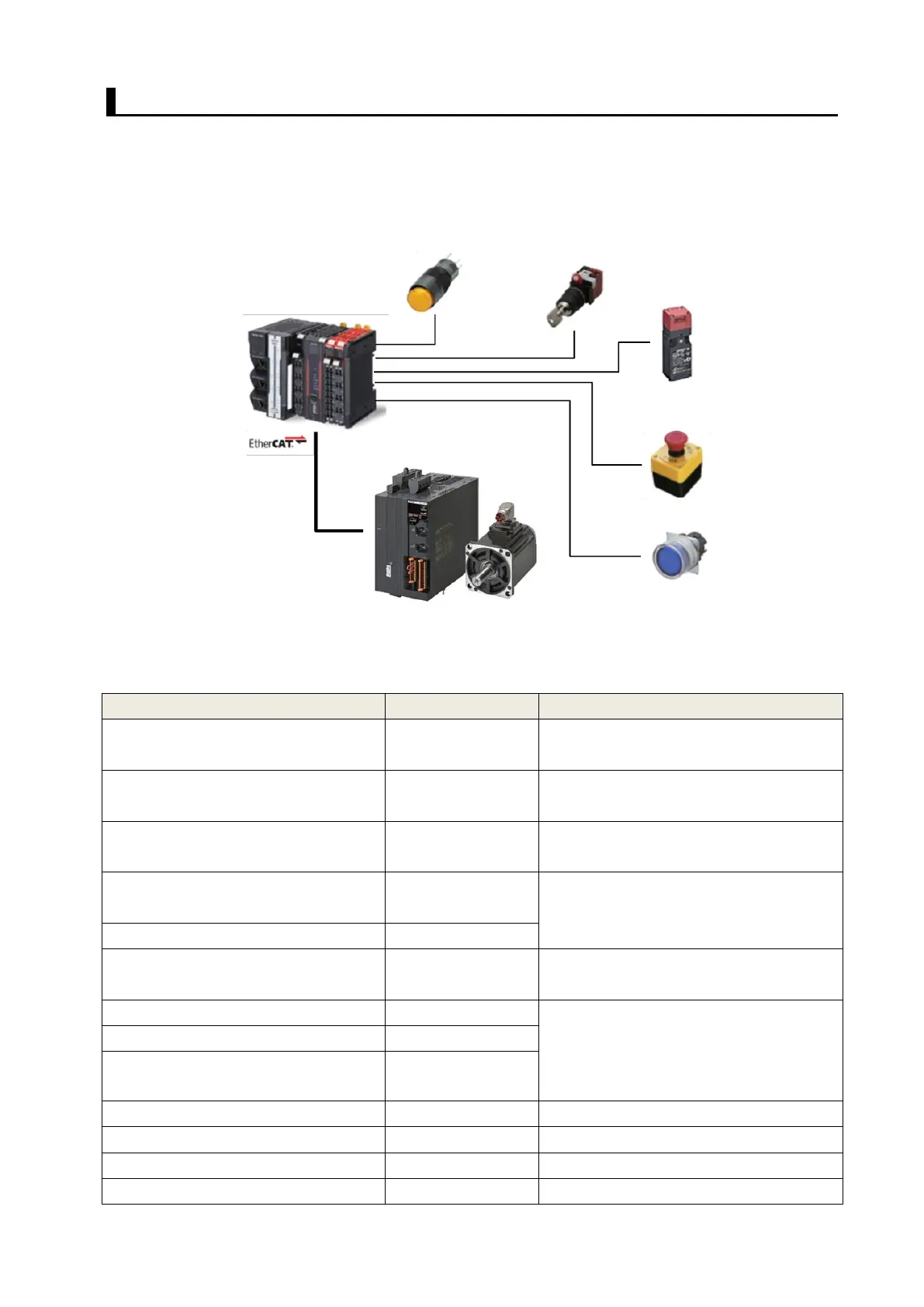
The following figure shows the system configuration and devices that are used in this Guide.
The system configuration is shown in the following figure.
⚫ Configuration Devices
The models of the devices that are described in this Guide are given in the following table. When
selecting devices for an actual application, refer to the device manuals.
NX-series NX1 CPU Unit
(Standard controller)
NX-series NX102 CPU Unit Hardware
User's Manual (W593)
Additional I/O Power Supply Unit
NX-series System Units User’s Manual
(W523)
NX-series Digital I/O Unit User’s Manual
(W521)
NX-series Safety CPU Unit
(Safety controller)
NX-series Safety Control Unit User's
Manual (Z930)
NX-series Safety Input Unit
Ethernet/EtherCAT Communications
Cable
1S-series AC Servomotors/Servo Drives
with Built-in EtherCAT Communications
and Safety Functionality User’s Manual
(I621)
Safety Key Selector Switch
Emergency Stop Pushbutton Switch
NX-series NX1 CPU Unit
Additional I/O Power Supply Unit
Digital Input Unit
NX-series Safety CPU Unit
NX-series Safety
Input Unit
AC Servo Drive
AC Servomotor
Safety Key Selector Switch
Emergency Stop Pushbutton
Switch
 Loading...