ZEN V2 Units
29
Precautions when Switching from Previous Units
• Previous models of Expansion I/O Units cannot be connected to V2 CPU Units.
• ZEN-8E1@R Expansion I/O Units with relay outputs need to be connected to a power supply.
• A ZEN-@C@D@-D-V2 CPU Unit with DC power supply cannot be connected to an Expansion I/O Unit with AC inputs.
• When connecting Expansion I/O Units with DC inputs to a CPU Unit with an AC power supply, the burst noise immunity will be 1 kV (IEC 61000-
4-4).
• There is no change to the 8 A per contact for relay output, but the total output for all contacts must be as follows:
Units with 10 I/O Points: 20 A max. (15 A max. for Communications-type CPU Units)
Units with 20 I/O Points: 40 A max.
Expansion I/O Units: 20 A max.
• Always use the ZEN-SOFT01-V4 Support Software for V2 CPU Units.
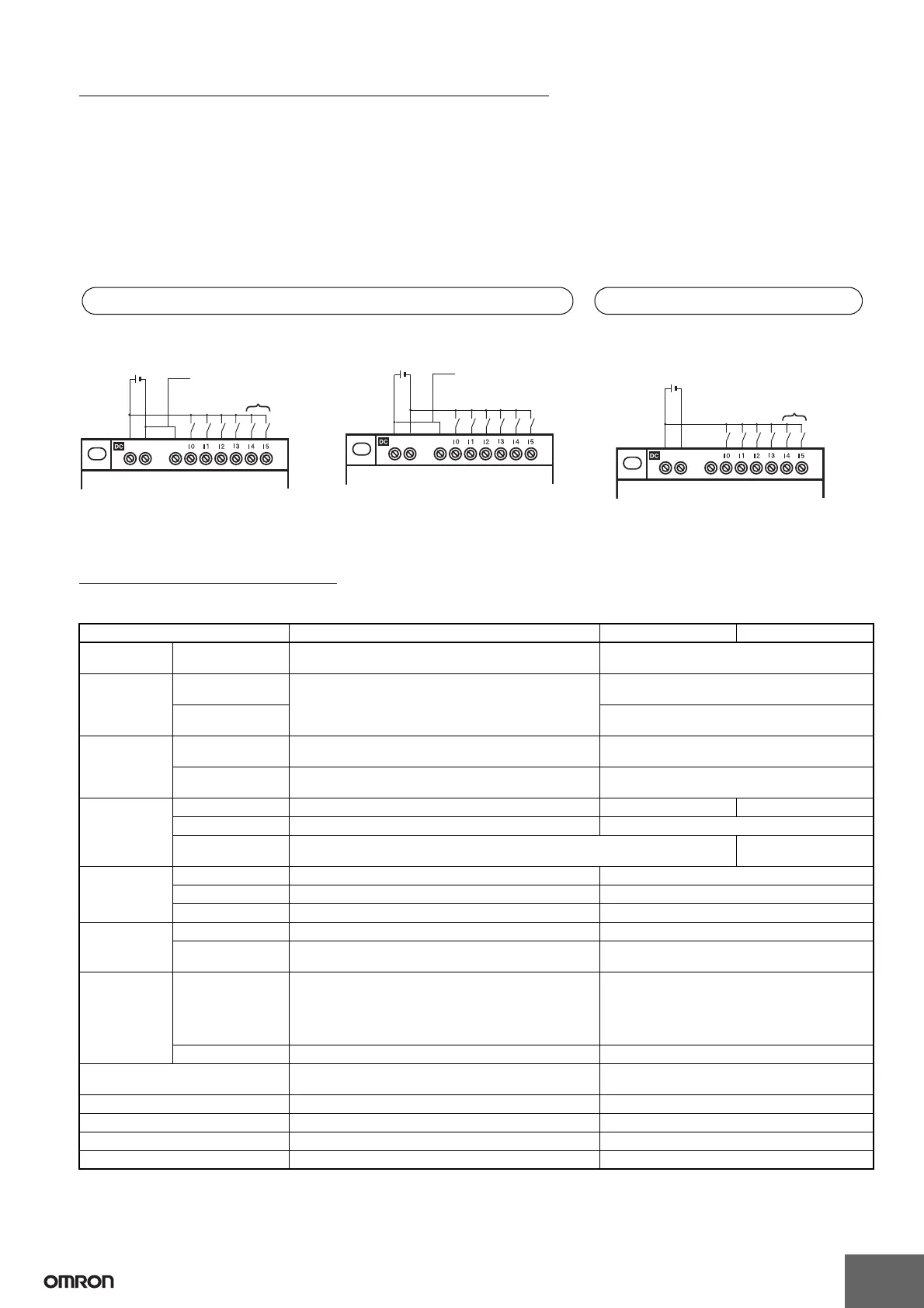
• Input wiring for CPU Units with DC power supplies differs from that for Pre-V1 CPU Units. Refer to the following diagrams.
■ Changes
Ratings and Specifications
CPU Units
Note: 1. Units with 20 I/O Points: I0 to I9
2. Units with 20 I/O Points: Ia to Ib
3. Refer to page 31 for details on compatible combinations of CPU Units and Expansion I/O Units.
24 VDC
COM wiring required.
Analog inputs possible.
+ −
COM
Negative (−) COM Wiring
CPU Unit with 10 I/O Points
Input
devices
24 VDC
+ −
COM
COM wiring required.
Positive (+) COM Wiring
Input
devices
CPU Unit with 10 I/O Points
24 VDC
+ −
NC
Analog inputs possible.
Input
devices
CPU Unit with 10 I/O Points
V2 and V1 CPU Units Pre-V1 CPU Units
COM wiring depends on whether a negative common or positive common is being used.
The input circuit common terminal is connected
internally to the negative (−) side of the power
supply circuit.
Note: I4 and I5 (Ia and Ib for CPU Units with 20 I/O
points) cannot be used as analog input terminals.
Item V2 Units V1 Units Pre-V1 Units
Rated power
supply voltage
Models with DC
power supply
10.8 to 28.8 VDC 20.4 to 26.4 VDC
Power
consumption
Models with AC
power supply
See Ratings on page 7. 30 VA max.
(with 3 Expansion I/O Units connected)
Models with DC
power supply
6.5 W max.
(with 3 Expansion I/O Units connected)
Inrush current Models with AC
power supply
Models with 10 I/O points: 4.5 A max.
Models with 20 I/O points: 4.5 A max.
40 A max.
Models with DC
power supply
Models with 10 I/O points: 30 A max.
Models with 20 I/O points: 30 A max.
20 A max.
DC inputs
I0 to I3
(See note 1.)
Input impedance 5.3 kΩ 5 kΩ 4.8 kΩ
ON voltage 8 VDC min. 16 VDC min.
Input common Independent common terminal Internally connected to
power supply terminal
DC inputs
I4 to I5
(See note 2.)
Input impedance 5.2 to 5.5 kΩ 5 kΩ
ON voltage 8 VDC min. 16 VDC min.
OFF voltage 3 VDC max. 5 VDC max.
Analog inputs
I4 to I5
(See note 2.)
Input impedance 100 kΩ min. 150 kΩ min.
Accuracy ±1.5% FS (at ambient operating temperature within
rated range)
±10% FS (at ambient operating temperature
within rated range)
Control
outputs
Relay outputs 8 A per output
Total for all outputs must be as follows:
Units with 10 I/O Points: 20 A max.
(15 A max. for Communications-type CPU Units)
Units with 20 I/O Points: 40 A max.
8 A per output
Transistor outputs 28.8 V max. 26.4 V max.
Timing accuracy of weekly and
calendar timers
±15 s or less per month (at 25°C) ±2 min per month
Mounting direction Standard (vertical) installation and horizontal installation Standard (vertical) installation
Terminal block tightening torque 0.565 to 0.6 N·m (5 to 5.3 in-lb) 0.5 to 0.6 N·m
Connectable Expansion I/O Units ZEN-8E1@ (See note 3.) ZEN-4E@ and ZEN-8E@
Case structure No heat slits Heat slits

 Loading...


