3 Basic Usage Procedures
3 - 2
E3NW-ECT EtherCAT Digital Sensor Communication Unit Operation Manual (E429)
3-1 Setup Examples and Basic
Procedure
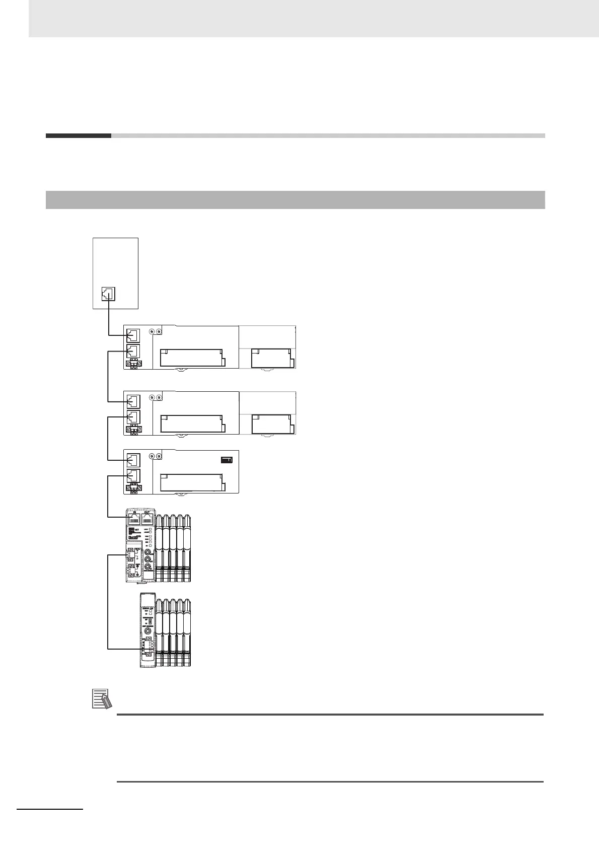
This section explains the setup method by using simple system setting examples.
Connect each of the following Slave Units to the EtherCAT Master Unit and make the settings.
Although it is not shown in the figure above, supply the unit power and the I/O power separately.
The setting example explained here is the basic setting of E3NW-ECT EtherCAT Sensor
Communication Units.
If more detailed settings are required in actual operation, refer to the manual of the EtherCAT
Master Unit. Moreover, if your system configuration includes Slave Units other than our products,
make the setting upon referring to the manual of the relevant Slave Units.
3-1-1 System Setting Examples
EtherCAT Master Unit
Digital I/O Slave Unit
GX-ID1611 (16 inputs)
+
Expansion Unit
XWT-ID16 (16 inputs)
Set the node address to 1.
Digital I/O Slave Unit
GX-OD1611 (16 outputs)
+
Expansion Unit
XWT-OD16 (16 outputs)
Set the node address to 2.
Analog Input Slave (4 inputs)
GX-AD0471
Set the node address to 5.
Sensor Communication Unit
E3NW-ECT
Set the node address to 6.
You can also connect up to eight E3NW-DS in one
E3NW-ECT. Up to 30 Sensor Amplifier Units can
be connected to the E3NW-ECT, and up to 10 Sensor
Amplifier Units can be connected to each E3NW-DS.
However, a total maximum of 30 Sensor Amplifier Units
can be connected in one E3NW-ECT system.
 Loading...