7 Function Specifications
7 - 2
E3NW-ECT EtherCAT Digital Sensor Communication Unit Operation Manual (E429)
7-1 I/O Data Allocation (PDO Mapping)
I/O data of Digital I/O Slave Units are allocated to the input/output areas of the I/O memory of the
EtherCAT Master Unit, respectively. For the detailed explanation of allocation method, refer to the
manual of EtherCAT Master Unit to be connected.
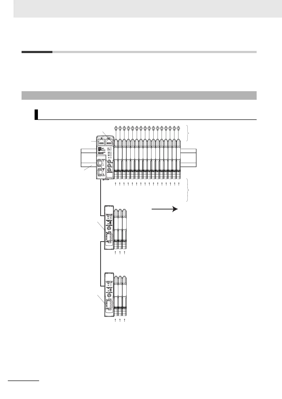
The Sensor Communication Unit identifies each connected Sensor Amplifier by its unit number. The
unit numbers for the Sensors are numbered in order starting from 1. Each Sensor Amplifier that is
assigned a unit number has an input 1 (Sensor output 1) and input 2 (Sensor output 2). The unit
numbers of the Sensor Amplifiers that are connected to a Distributed Sensor Unit are numbered
sequentially, in the order shown below, following the unit numbers of the Sensor Amplifiers that are
connected to the Sensor Communication Unit.
7-1-1 Input Data Allocation
Sensor Numbers
Unit numbers are assigned in order
from 1 going from left to right.
Amplifier Units
Sensor Communication
Unit
Distributed
Sensor Unit 1
Distributed
Sensor Unit 2
DIN Track
Sensor Heads
Connectors
Unit 1
Unit 2
Unit 3
Unit 4
Unit 5
Unit 6
Unit 7
Unit 8
Unit 9
Unit 10
Unit 11
Unit 12
Unit 13
Unit 14
Unit 15
Unit 16
Unit 17
Unit 18
Unit 19
Unit 20
Unit 21
Unit 22
 Loading...