26
4. Coordinate System
This chapter describes the coordinate system handled by the robot vision application.
4.1. Name of Coordinate System
The robot coordinate system of the Vision Sensor uses the name shown in the table
below.
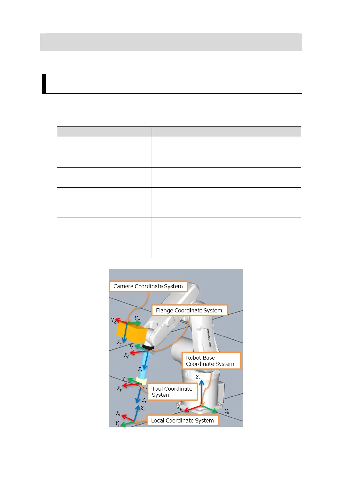
Robot Base Coordinate
Coordinate system with the robot base as the
User-defined coordinate system
Flange Coordinate system Coordinate system defined on the flange surface
Tool Coordinate System The coordinate system is defined in the tool
center point by offsetting the origin of the
flange coordinates system.
Camera Coordinate System With the optical center of the camera as the
starting point, the X and Y axes are the
horizontal and vertical directions of the image,
and the Z axis is the optical axis of the camera.

 Loading...


