G9SA
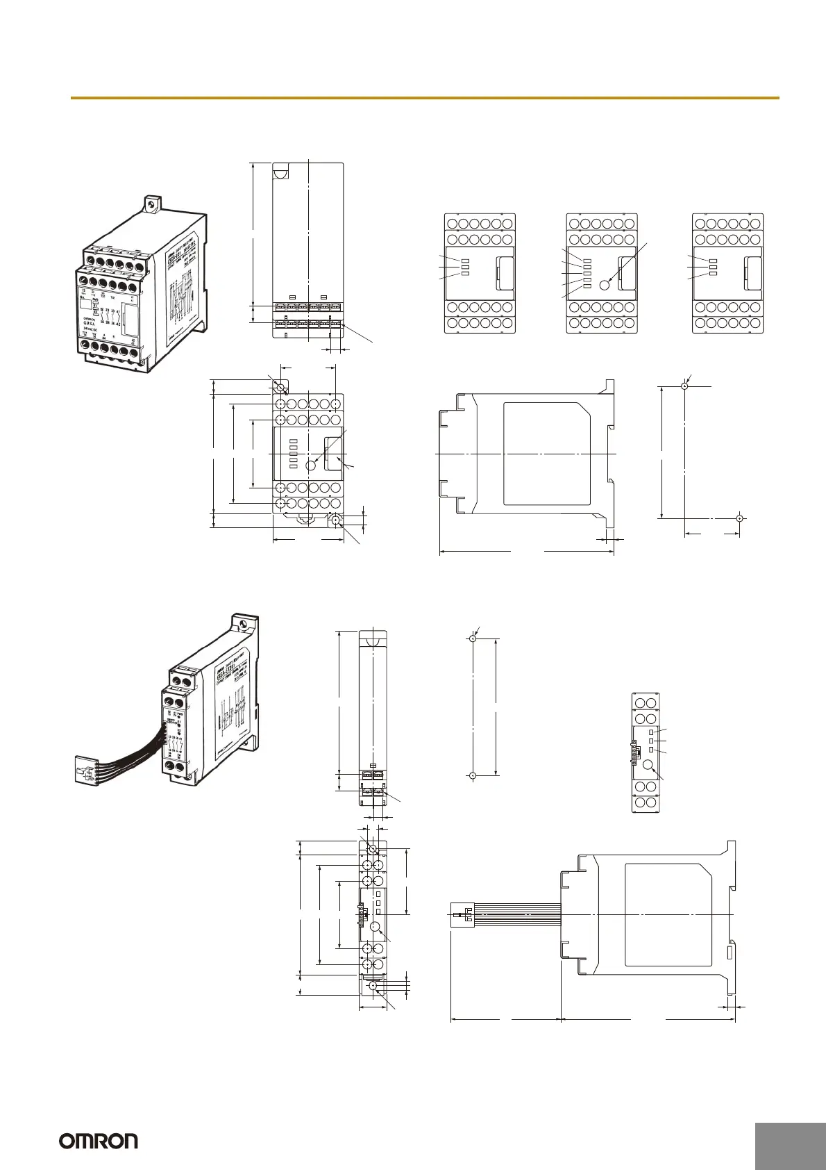
Dimensions
Note: All units are in millimeters unless otherwise indicated. The diagrams are drawn in perspective.
Terminal Arrangement
Mounting Holes
Two, 4.2 dia. or M4
Terminal Arrangement
Mounting Holes
Two, 4.2 dia. or M4
4.6 dia.
45 max.
76 max.
111 max.
4.6 dia.
111 max.
76 max.
17.5 max.
Connector cover
(see note 2)
Eight, M3
G9SA-301
G9SA-501
G9SA-321-T@
G9SA-TH301
G9SA-EX301
G9SA-EX031-T@
G9SA-301: Twenty, M3
G9SA-501: Twenty-four, M3
G9SA-321-T@: Twenty-four, M3
G9SA-TH301: Twenty-one, M3
OFF-delay time
setting switch
(see note 1)
Note 1: The OFF-delay time setting switch is
found on the G9SA-321-T@ only.
OFF-delay time
setting switch
(see note)
G9SA-EX301
G9SA-EX031-T@
OFF-delay time
setting switch
(see note)
2: The K1 to K4 indicators light when the NO contacts of
internal relays K1 to K4 close.
3: Do not remove unless an Expansion Unit is being used.
Note 1: The OFF-delay time setting switch is
found on the G9SA-EX031-T@ only.
2: The K1 and K2 indicators light when
the NO contacts of internal relays K1
and K2 close.
13 23 33 41
14 24 34 42
T11 T12 T31 T32 T23
A1
T21 T22
ABPEA2
13 23 33 43 53 61
14 24 34 44 54 62
T11 T12 T31 T32 T23
A1
T21 T22
ABPEA2
13 23 33 41
14 24 34 D 42
T11 T12 T13 T31 T32
A1
T21 T22 T23
CPEA2
4363
9
35
±0.3
7 × 5=35
5.9
R2.3
5
5.6
9
10.5
91
G9SA-301 G9SA-501
G9SA-321-T@
G9SA-TH301
OFF-delay
time setting
switch
(See note 1.)
84±0.3
PWR (green)
K1 (green)
K2 (green)
PWR (green)
K1 (green)
K2 (green)
PWR (green)
K1 (green)
K2 (green)
K3 (green)
K4 (green)
4133
2313
2414
4234
43
42
87
±0.3
5.6
R2.3
5
70
63
9
13.2
10.5
91
5.9
7
PWR (green)
K1 (green)
K2 (green)
http://www.ia.omron.com/
11
(c)Copyright OMRON Corporation 2007 All Rights Reserved.
Artisan Technology Group - Quality Instrumentation ... Guaranteed | (888) 88-SOURCE | www.artisantg.com
 Loading...


