C Circuit Design
A Load Circuits
C-A-1 Load Switching
In actual Relay operation, the switching capacity, electrical durability,
and applicable load will vary greatly with the type of load, the
ambient conditions, and the switching conditions. Confirm operation
under the actual conditions in which the Relay will be used.
A Resistive Loads and Inductive Loads
The switching power for an inductive load will be lower than the
switching power for a resistive load due to the influence of the
electromagnetic energy stored in the inductive load.
B Switching Voltage (Contact Voltage)
The switching power will be lower with DC loads than it will with AC
loads. Applying voltage or current between the contacts exceeding
the maximum values will result in the following:
1. The carbon generated by load switching will accumulate around
the contacts and cause deterioration of insulation.
2. Contact deposits and locking will cause contacts to malfunction.
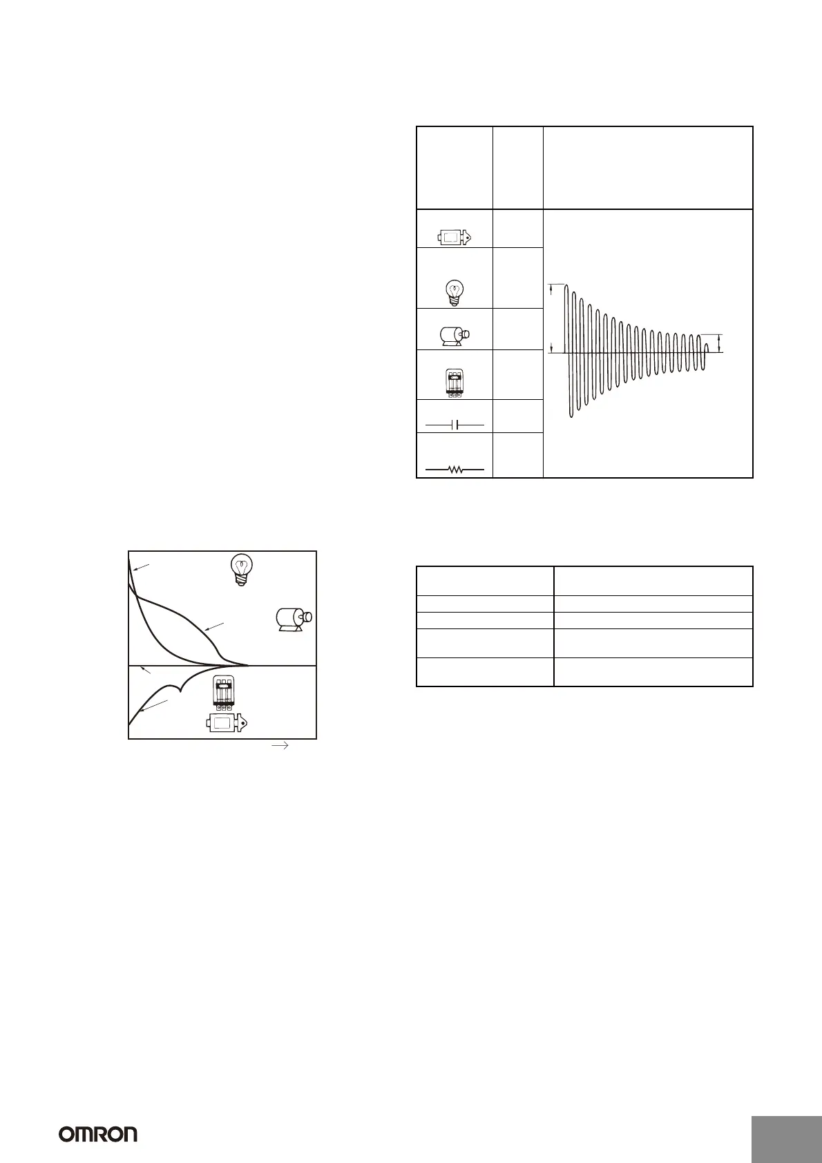
C Switching Current (Contact Current)
Current applied to contacts when they are open or closed will have a
large effect on the contacts. For example, when the load is a motor or
a lamp, the larger the inrush current, the greater the amount of
contact exhaustion and contact transfer will be, leading to deposits,
locking, and other factors causing the contacts to malfunction.
(Typical examples illustrating the relationship between load and
inrush current are given below.) If a current greater than the rated
current is applied and the load is from a DC power supply, the
connection and shorting of arcing contacts will result in the loss of
switching capability.
DC Loads and Inrush Current
AC Loads and Inrush Current
C-A-2 Electrical Durability
Electrical durability will greatly depend on factors such as the coil
drive circuit, type of load, switching frequency, switching phase, and
ambient atmosphere. Therefore be sure to check operation in the
actual application.
-
-3 Failure Rates
The failure rates provided in this catalog are determined through
tests performed under specified conditions. The values are reference
values only. The values will depend on the operating frequency, the
ambient atmosphere, and the expected level of reliability of the
Relay. Be sure to check relay suitability under actual load conditions.
Incandescent bulb
(approx. 6 to 11 times
steady-state current)
Motor
(approx. 5 to
10 times steady-
state current)
Resistive load
Relay,
solenoid
Time
t
Current
Type of load Ratio of
inrush
current
to
steady-
state
current
Waveform
Solenoid Approx.
10
Incandes-
cent bulb
Approx.
10 to 15
Motor Approx.
5 to 10
Relay Approx.
2 to 3
Capacitor Approx.
20 to 50
Resistive
load
1
Coil drive circuit Rated voltage applied to coil using
instantaneous ON/OFF
Type of load Rated load
Switching frequency According to individual ratings
Switching phase
(for AC load)
Random ON, OFF
Ambient atmosphere According to JIS C5442 standard test
conditions
Steady
state
current
Inrush current
http://www.ia.omron.com/
C-5
(c)Copyright OMRON Corporation 2007 All Rights Reserved.
Artisan Technology Group - Quality Instrumentation ... Guaranteed | (888) 88-SOURCE | www.artisantg.com
 Loading...


