G9SA
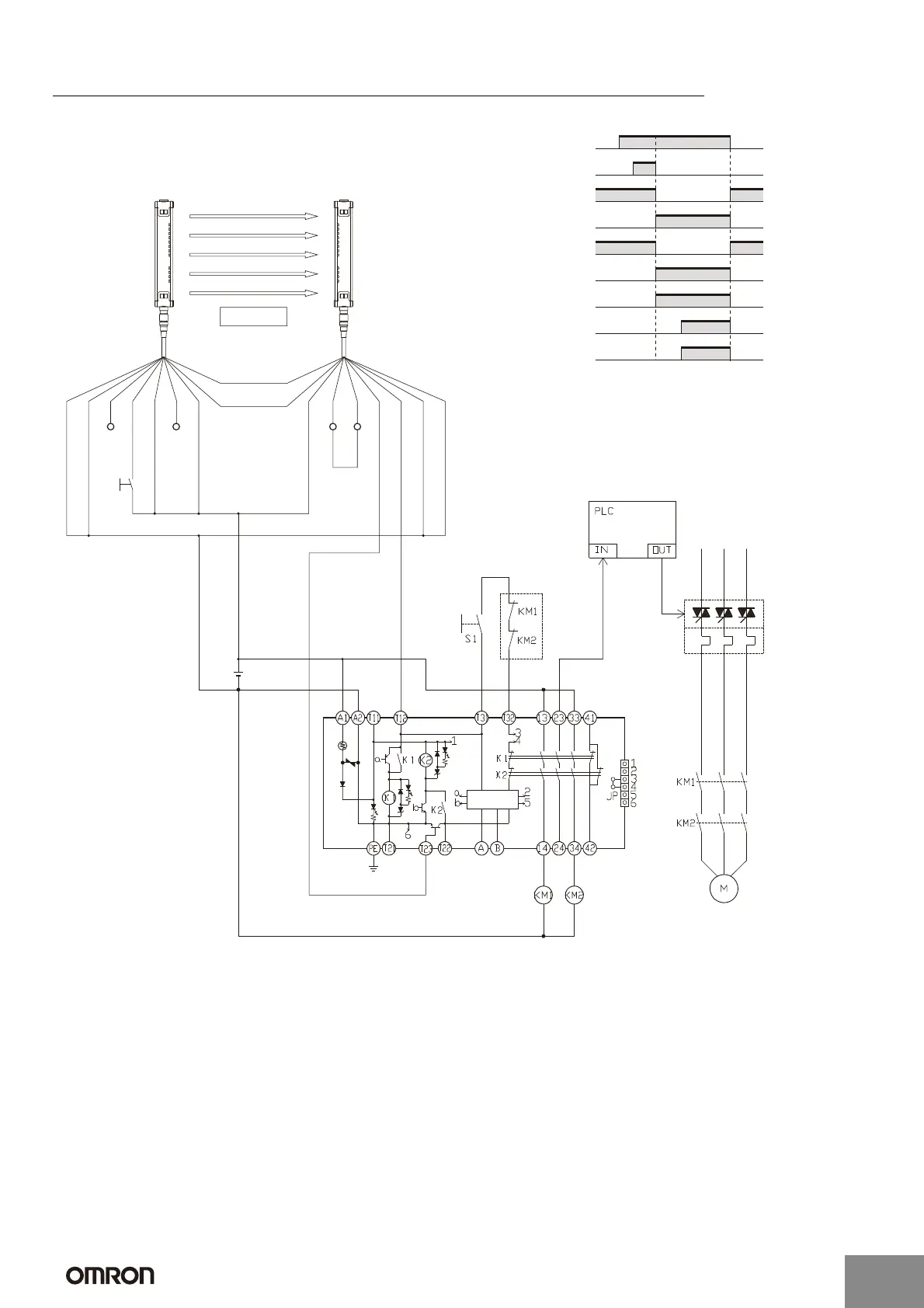
G9SA-301 (24 VAC/VDC) with 2-channel Safety Sensor/Manual Reset
KM3
E1
Feedback loop
Reset switch S1
Timing Chart
PLC input
PLC output
KM3
F3SN-A Incident
Interrupted
K1 and K2
(NC)
K1 and K2
(NO)
KM1 and KM2
(NC)
KM1 and KM2
(NO)
F3SN-A: Safety area sensor
S1: Reset switch
KM1 and KM2: Magnetic Contactor
KM3: G3J Solid-state Contactor (G3J)
M: 3-phase motor
E1: 24-VDC Power Supply (S82K)
Shield
0V (Blue)
OSSD2 (White)
OSSD1 (Green)
Auxiliary (Yellow)
EDM input (Red)
+24V (Brown)
+24V (Brown)
Open
Interlock selection
input (White)
Reset input (Yellow)
Test input (Green)
Open
(Red)
0V (Blue)
Shield
RS-485(A) (Gray)
(See
note 2.)
RS-485(B) (Pink)
Note: 1. This circuit achieves EN954-1 Safety Category 4.
2. The F3SN-A auxiliary output wiring is shown for dark-ON
operation.
TH
SA
F3SN-A
ReceiverEmitter
Control
circuit
http://www.ia.omron.com/
8
(c)Copyright OMRON Corporation 2007 All Rights Reserved.
Artisan Technology Group - Quality Instrumentation ... Guaranteed | (888) 88-SOURCE | www.artisantg.com
 Loading...


