Multifunction Digital Timer H5CX-A/-L 7
Connections
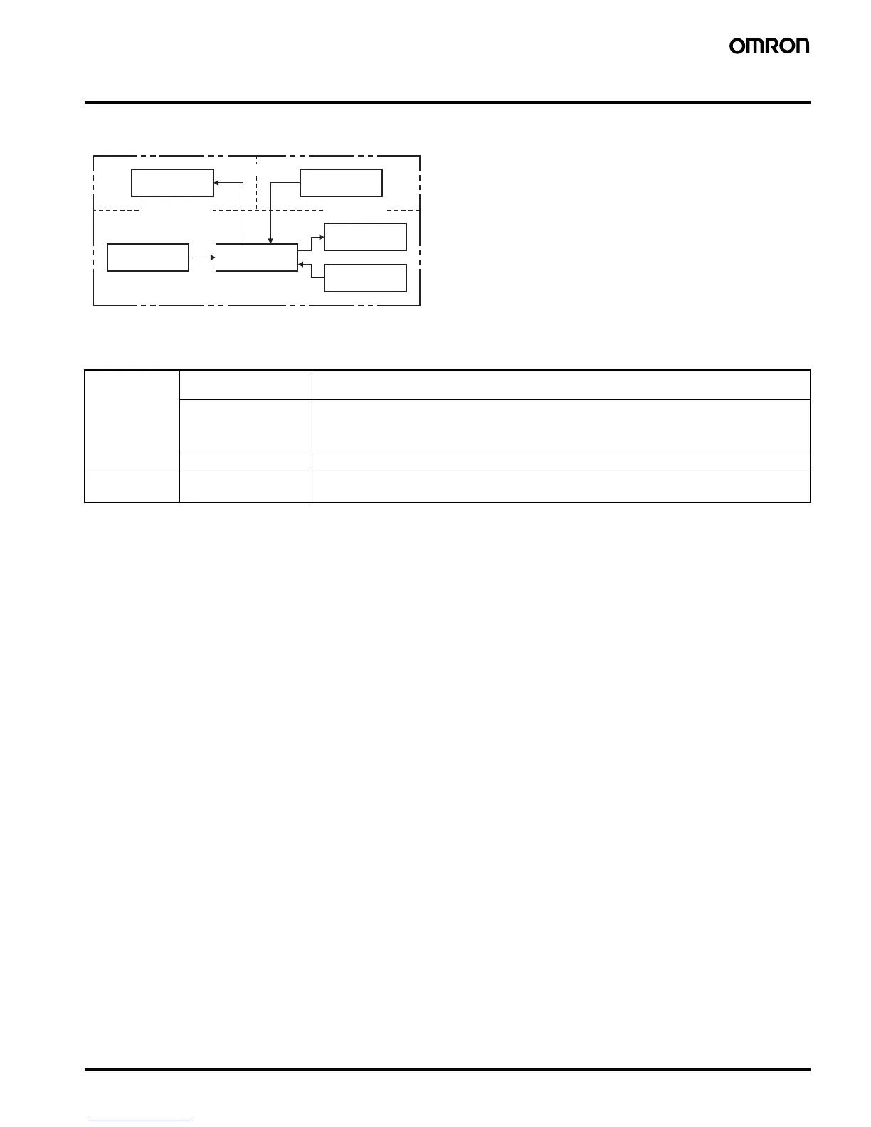
■ Block Diagram
Note: Power circuit is not insulated from the input circuit, except for H5CX-A11/-A11S, which have basic insulation.
■ I/O Functions
Output circuit
Input circuit
Internal control
circuit
Power supply
circuit
Display circuit
Key switch
circuit
(See note.)
(Basic insulation)
(Basic insulation)
Inputs Start signal Stops timing in A-2 and A-3 (power ON delay) modes.
Starts timing in other modes.
Reset Resets present value. (In elapsed time mode, the present value returns to 0; in remaining time
mode, the present value returns to the set value.)
Count inputs are not accepted and control output turns OFF while reset input is ON.
Reset indicator is lit while reset input is ON.
Gate Inhibits timer operation.
Outputs Control output (OUT) Outputs take place according to designated operating mode when timer reaches corresponding set
value.
 Loading...