42
130 kg
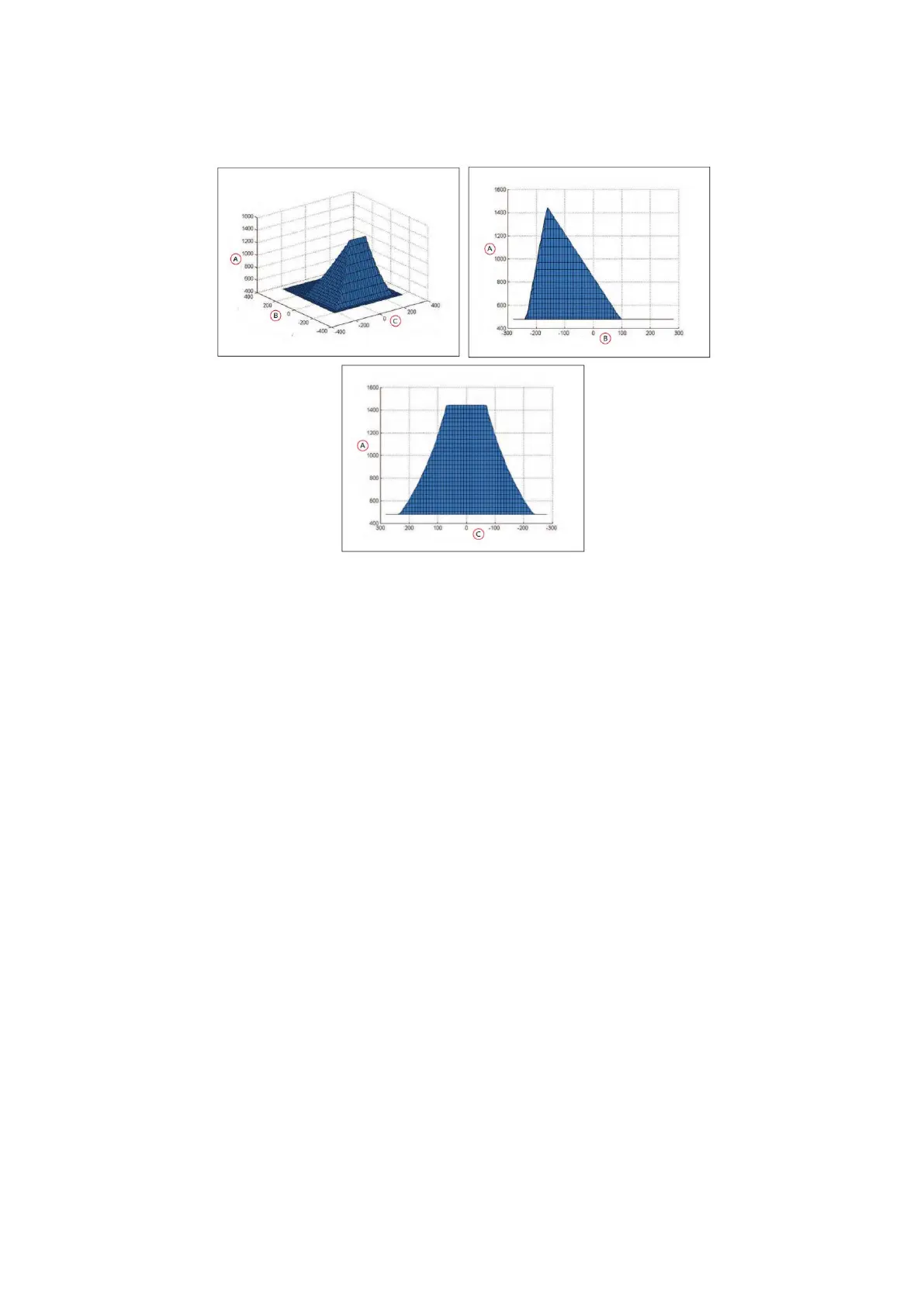
Figure 14: Center of Gravity Graphs, 130 kg
7.3 Payload-Related Tradeoffs
If you have to extend your center of gravity beyond the guidelines given here, you will need to adjust
various parameters in the MobilePlanner software to compensate for that.
Contact your robot provider to get a new set of plots based on parameters that differ from those used to
produce the plots shown here.
In general, lowering the maximum accel, decel, and rotation speeds will be required. Refer to Acceleration,
Deceleration, and Rotation Limits in the User’s Manual.
7.4 Connections Between Platform and Payload Structure
The LD platform provides a variety of I/O and power connections, which you can use to make your AMR
more effective.
Operator Panel
The Operator screen, E-Stop, Brake-release, ON, and OFF can be "moved" using a single connector (the
HMI Panel connector). This allows you to put many of the more common operator controls somewhere on
your payload structure with just one cable.
 Loading...


