44
8 Connectivity
Most of the connections that are available to the user are in the payload bay, which is the space between
the platform and any payload structure placed on top of it. These include I/O and power connections. Some
are required; others are available if needed. The two exceptions are the Joystick port, and the Maintenance
Ethernet port, which are located under a small access panel on the left side of the LD platform, in the
upper-right corner. Both of these ports have a second, connected port inside the payload bay. See Figure
14. The LD Cart Transporter models have addition electronics in the payload bay that control the automated
latching system, and the user interface at the top of the post at the rear of the platform. Connections that
differ from the base LD Platform are addressed below.
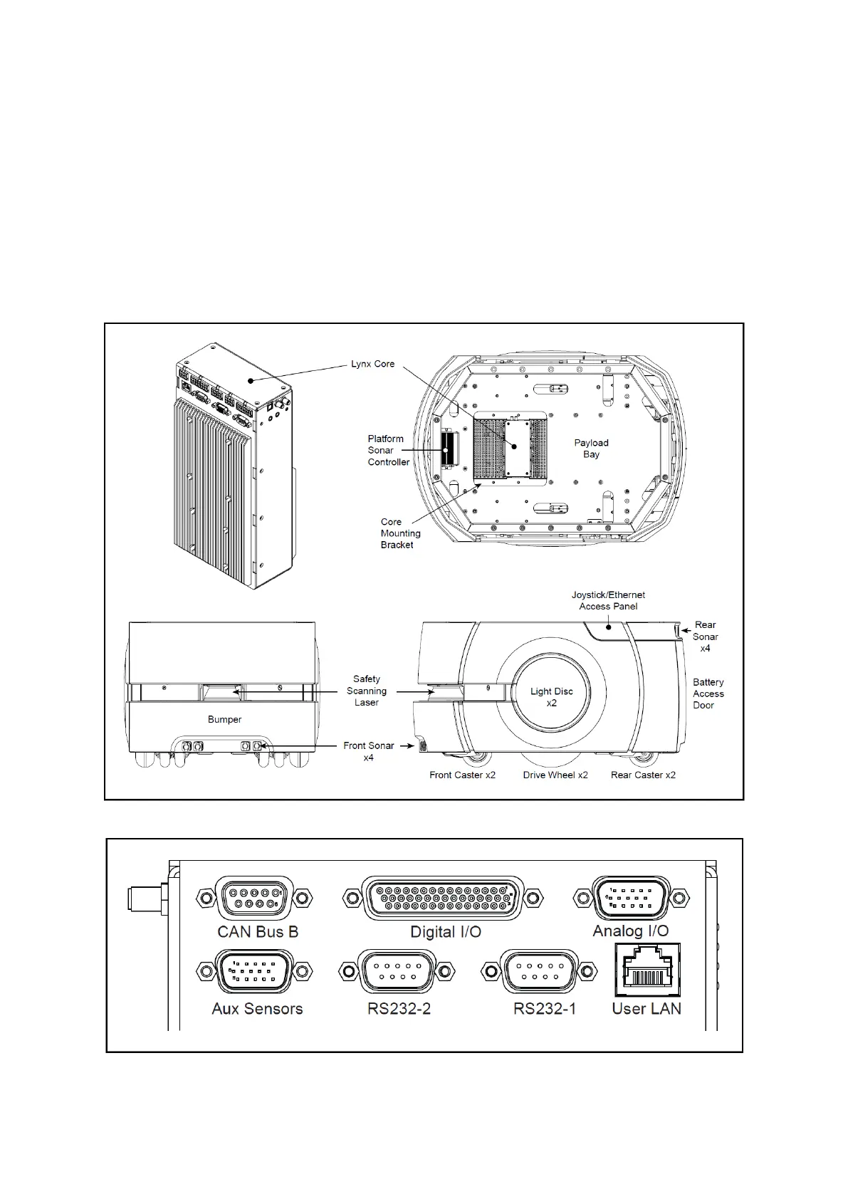
Figure 12: Location of Parts on the Platform
Figure 13: Front Upper Core
 Loading...


