6 Incremental Encoder Input Units
6 - 40
NX-series Position Interface Units User’s Manual (W524)
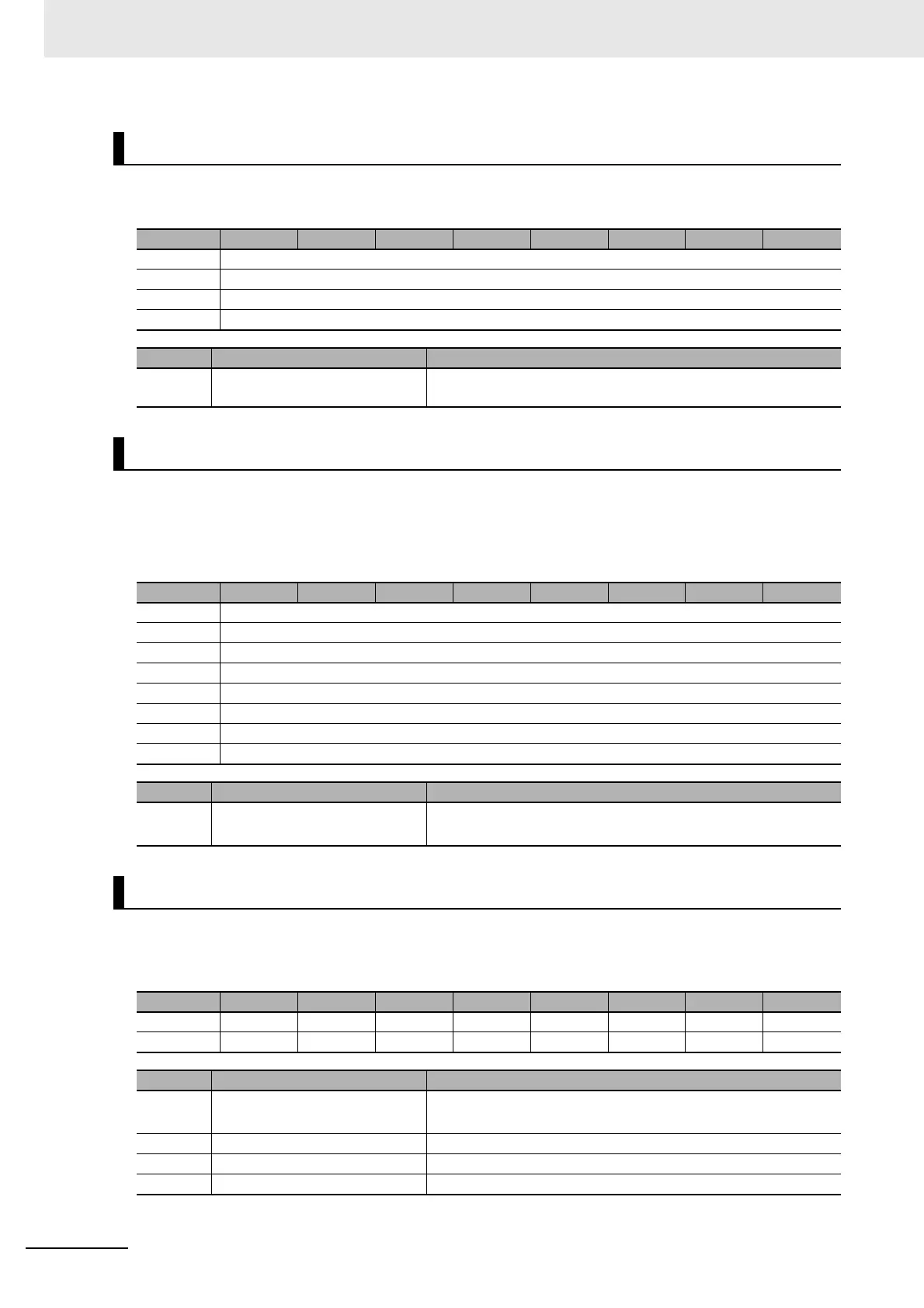
The bit configuration of the Pulse Period Measured Value parameter is given in the following table.
n: Channel number
The bit configuration of the Time Stamp parameter is given in the following table.
Refer to 6-9-12 Time Stamping on page 6-75 for details on time stamps.
Note An EtherCAT Coupler Unit with unit version 1.1 or later is required.
n: Channel number
The bit configuration of the Encoder Counter Operation Command parameter is given in the following
table.
n: Channel number
Pulse Period Measured Value
Byte Bit 7 Bit 6 Bit 5 Bit 4 Bit 3 Bit 2 Bit 1 Bit 0
0 PPVn (Chn Pulse Period Measured Value LL)
+1 PPVn (Chn Pulse Period Measured Value LH)
+2 PPVn (Chn Pulse Period Measured Value HL)
+3 PPVn (Chn Pulse Period Measured Value HH)
Abbr. Data Description
PPVn Chn Pulse Period Measured
Value
This contains the pulse period measured value for channel n.
Time Stamp
Byte Bit 7 Bit 6 Bit 5 Bit 4 Bit 3 Bit 2 Bit 01 Bit 0
0 TMSn (Chn Time Stamp, 1st byte)
+1 TMSn (Chn Time Stamp, 2nd byte)
+2 TMSn (Chn Time Stamp, 3rd byte)
+3 TMSn (Chn Time Stamp, 4th byte)
+4 TMSn (Chn Time Stamp, 5th byte)
+5 TMSn (Chn Time Stamp, 6th byte)
+6 TMSn (Chn Time Stamp, 7th byte)
+7 TMSn (Chn Time Stamp, 8th byte)
Abbr. Data Description
TMSn Chn Time Stamp Contains the time stamp for when Chn changed.
It stores the DC time. (Unit: ns)
Encoder Counter Operation Command
Byte Bit 7 Bit 6 Bit 5 Bit 4 Bit 3 Bit 2 Bit 1 Bit 0
0 ZSCRn ERCRn ZSENn ERENn PSETn INLAn INRSn CENn
1 --- --- --- --- --- --- --- ---
Abbr. Data Description
CENn Counter Enable 1: Enable counter command.
0: Disable counter command.
INRSn Internal Reset Execution 0 to 1: Reset of present value started.
INLAn Internal Latch Execution 0 to 1: Internal latch started.
PSETn Preset Execution 0 to 1: Preset of present value started.
 Loading...


