9 - 9
9 Application Example
NX-series Position Interface Units User’s Manual (W524)
9-3 Setting Examples
9
9-3-3 I/O Assignments and Settings
This section describes the axis settings and device variable settings that are required for the previous
example system configuration.
For this example, we will assign some inputs from the Pulse Output Unit, which has I/O, and Digital I/O
Units to MC Function Module axes.
Inputs and outputs that are not assigned to axes are assigned to device variables through I/O ports.
Precautions for Correct Use
• The MC Function Module in the NJ/NX-series Controller does not support a RUN output or
alarm reset output to the Servo Drive or the detection of alarm and positioning completion
inputs from the Servo Drive. These inputs and outputs must be handled in the user program
through the use of device variables that correspond to the connected inputs and outputs.
• The Servo Drive alarm status requires some time to recover after the alarm reset output is
turned ON (i.e., when the reset input on the Servo Drive is turned ON). When you work with
the alarm reset output in the user program, consider the time required to clear the alarm in
the Servo Drive and build an output-holding circuit.
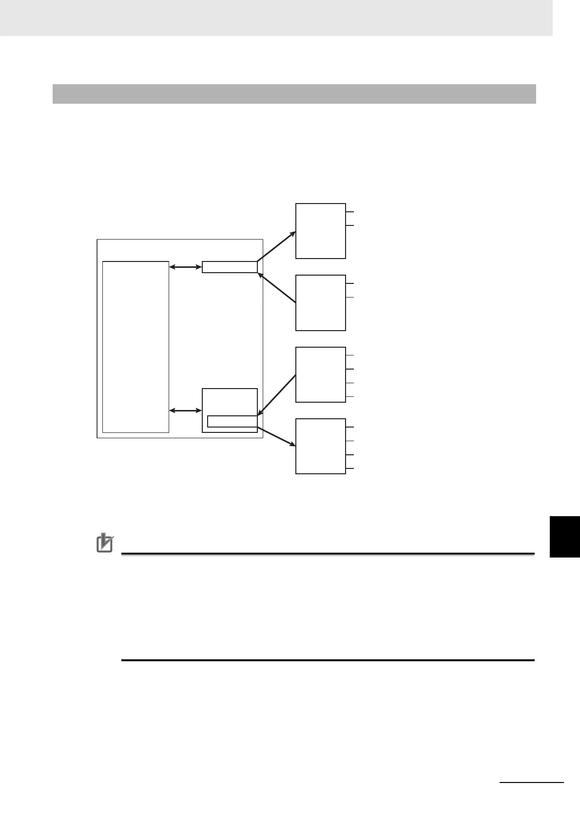
9-3-3 I/O Assignments and Settings
Pulse output A
Pulse output B
O0
I0
CCW
CW
Error counter reset output
Latch input
NX-PG0122 Pulse Output Unit
IN0
IN1
IN2
IN3
Immediate stop input
Negative limit input
Positive limit input
Home proximity input
NX-ID3417 Digital Input Unit
IN0
IN1
Positioning completion input
Error input
NX-ID3417 Digital Input Unit
OUT0
OUT1
Error reset output
RUN output
NX-OD4256 Digital Output Unit
Motion Control
Function Module
Axes
Device variables
User program
NJ501-1500 (Controller)
 Loading...


