7 - 11
7 SSI Input Units
NX-series Position Interface Units User’s Manual (W524)
7-5 Terminal Block Arrangement
7
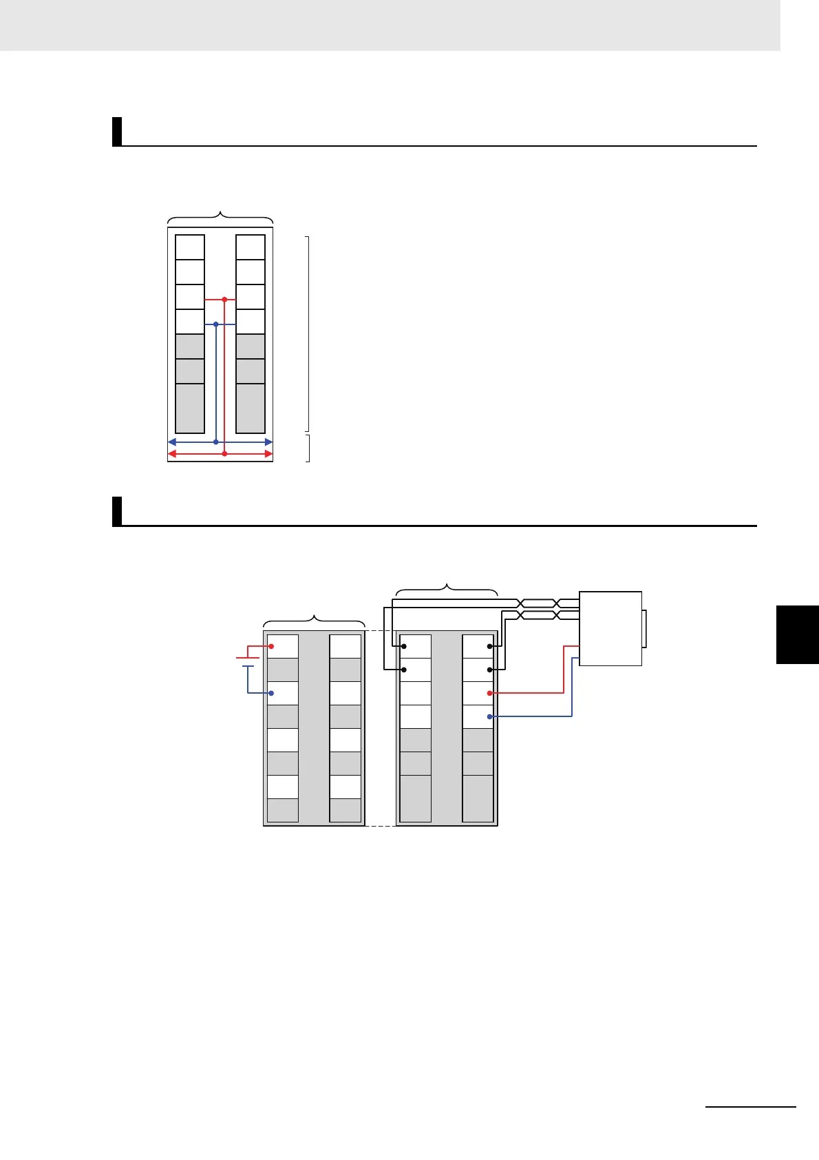
7-5-1 NX-ECS112
The following diagram shows the internal power supply wiring.
The following is a wiring example.
Note To supply power to connected external devices, connect an 24-VDC I/O power supply to the Communi-
cations Coupler Unit or an Additional I/O Power Supply Unit to supply power to the SSI Input Unit.
Internal Power Supply Wiring Diagram
Wiring Example
24 V
0 V
C+
C-
IOV
IOG
NC
NC
D+
D-
IOV
IOG
NC
NC
Terminal block
NX bus connector
SSI Input Unit
Note The I/O power is supplied from the I/O power supply connected
to the I/O power supply terminals on the Communications Cou-
pler Unit or an Additional I/O Power Supply Unit.
C+
C-
IOV
IOG
NC
NC
D+
D-
IOV
IOG
NC
NC
IOV
IOV
IOG
IOG
IOV
IOV
IOG
IOG
I/O power supply
(24 VDC)
Additional I/O
Power Supply Unit
SSI Input Unit
SSI
encoder
 Loading...


