4 - 29
4 System Design
G5-series Linear Motors/Servo Drives With Built-in EtherCAT Communications
4-4 Noise Reduction
4
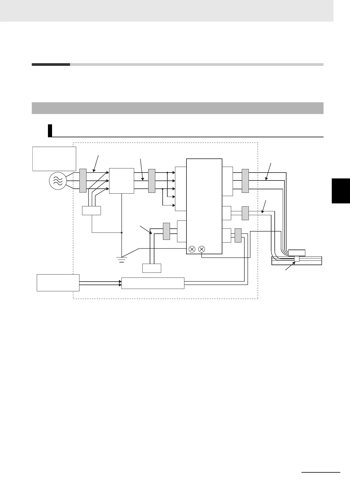
4-4-1 Wiring Method
4-4 Noise Reduction
This section provides a wiring example with a G5-series Linear Motor as a means to prevent anticipated
noise interference with peripheral equipment when a linear system is installed.
*1 Not required for single-phase models with a 100-VAC input.
Note For models with a single-phase power supply input, the main circuit power supply input terminals are L1 and
L3.
• Use a ground plate for the frame ground for each unit, as shown in the above diagrams, and ground
to a single point.
• Use ground lines with a minimum thickness of 3.5 mm
2
, and arrange the wiring so that the ground
lines are as short as possible.
• A no-fuse breaker, surge absorber, and noise filter should be positioned near the input terminal block
(ground plate), and I/O lines should be separated and wired at the shortest distance.
4-4-1 Wiring Method
100-VAC and 200-VAC Input Servo Drive Models
(3)
(4)
(1)
(2)
(6)
(5)
(7)
(8)
FC2
ECAT
IN
FC1
TB
L3
L1C
L2C
Single-phase:
100 VAC
SG
*1
NF
FC1 FC1
SD
FC3
FC1
CNA
CN1
CNB
CN4
U
V
W
LM
L1
L2
Single-phase:
100 VAC
3-phase: 200 VAC
Controller
SCL
 Loading...