S8VS
19
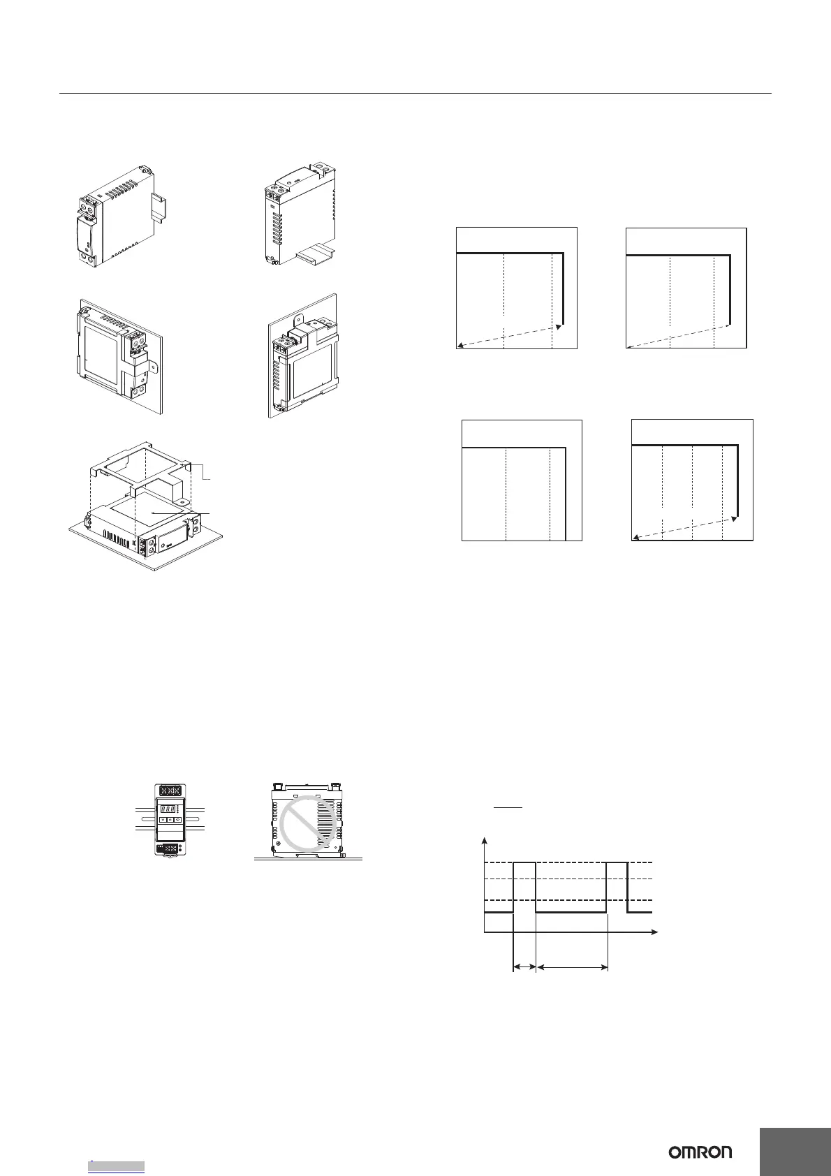
Mounting
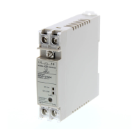
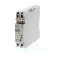
15 and 30 W
Note: 1. Improper mounting will interfere with heat dissipation and
may occasionally result in deterioration or damage of
internal parts. Use the Product within the derating curve for
the mounting direction that is used. Do not use the Power
Supply mounted in any way not shown above.
2. Use a mounting bracket (S82Y-VS30P, sold separately)
when the Product is mounted horizontally.
3. Heat dissipation will be adversely affected. When the
Product is mounted facing horizontally, always place the
side with the label facing horizontally.
4. Use PFP-M End Plates on the top and bottom of the Power
Supply when mounting horizontally on a DIN rail.
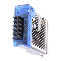
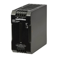
60, 90, 120, 180, 240, and 480 W
Note: Improper mounting will interfere with heat dissipation and may
occasionally result in deterioration or damage of internal parts.
It may also result in failure of the maintenance forecast monitor
function. Use the standard mounting method only.
Overload Protection
The load and the power supply are automatically protected from
overcurrent damage by this function. Overload protection is activated
if the output current rises above 105% (151% with S8VS-48024@) of
the rated current.
When the output current returns within the rated range overload
protection is automatically cleared.
Note: 1. Internal parts may occasionally deteriorate or be damaged
if a short-circuited or overcurrent state continues during
operation.
2. Internal parts may possibly deteriorate or be damaged if the
Power Supply is used for applications with frequent inrush
current or overloading at the load end. Do not use the Power
Supply for such applications.
Peak Output Current (S8VS-48024@ only)
The boost current is a temporary current that exceeds the rated current.
However, it should meet the following four boost current conditions.
• Time that the boost current flows: t1 ≤ 10 s
• The boost current: Ip ≤ Maximum boost current
• The average output current: Iave ≤ Rated output current
• The time ratio of the boost current flow: Duty ≤ 30%
• Do not allow a boost current to flow for more than 10 s.
Do not allow the duty to exceed 30%. These conditions may
damage the Power Supply.
• Do not allow the average current for one cycle of the boost current
to exceed the rated current. The Power Supply may be damaged.
• Derate the boost current and the average output current loads
according to the ambient operating temperature and mounting
direction.
Face-up mounting with DIN rail
S82Y-VS30P
Side with label
Horizontal mounting with S82Y-VS30P*
Standard mounting with DIN rail
Face-up mounting with S82Y-VS30P
Standard mounting with S82Y-VS30P
Note: The Side-mounting Bracket can be mounted from either side.
Upper
Upper
Standard mounting Face-up mounting
Correct Incorrect
0 10050
Output current (%)
Output voltage (V)
Intermittent
operation
15-W/30-W Models
The values shown in the above diagrams are for reference only.
050100
Output current (%)
Output voltage (V)
Intermittent operation
60-W/90-W Models
050100
Output current (%)
Output voltage (V)
120-W/180-W/240-W Models
The values shown in the above diagrams are for reference only.
Output current (%)
Output voltage (V)
480-W Models
0 100 15050
Intermittent
operation
Duty=
t1 + t2
t1
× 100 [%] ≤ 30%
[A]
Ip: Boost current
Rated current
lave: Average current
t2
t1
output current
Downloaded from Arrow.com.Downloaded from Arrow.com.Downloaded from Arrow.com.Downloaded from Arrow.com.Downloaded from Arrow.com.Downloaded from Arrow.com.Downloaded from Arrow.com.Downloaded from Arrow.com.Downloaded from Arrow.com.Downloaded from Arrow.com.Downloaded from Arrow.com.Downloaded from Arrow.com.Downloaded from Arrow.com.Downloaded from Arrow.com.Downloaded from Arrow.com.Downloaded from Arrow.com.Downloaded from Arrow.com.Downloaded from Arrow.com.Downloaded from Arrow.com.
 Loading...